PTP & SyncE
This document describes Terragraph's software implementations for the IEEE 1588v2 (Precision Time Protocol, or PTP) and Synchronous Ethernet (SyncE) protocols, which are used to meet the synchronization requirements of cellular networks.
Overview
A common requirement for cellular backhaul is to support IEEE 1588 (PTP) and SyncE transport for time (phase) and frequency synchronization. Although PTP can be used for both frequency and phase synchronization, in telecom networks it is rarely used for both in the same network. Instead, in telecom networks PTP is typically used only for phase synchronization in conjunction with SyncE for frequency synchronization, or only used for frequency synchronization in systems that do not require phase sync (e.g. FDD networks).
The ITU device characteristics (conformance tests) for telecom clocks in G.8273.2 and G.8273.3 explicitly state that the PTP clock's frequency reference is provided by the physical layer based on ITU G.8262 EEC-Option 1 (SyncE). Performance requirements for telecom clocks without SyncE for frequency are for further study.
The block diagram below shows Terragraph's reference implementation described in this document.

IEEE 1588/PTP Distributed Transparent Clock
Terminology
- PTP: IEEE 1588v2 Precision Time Protocol
- OC: 1588/PTP Ordinary Clock
- BC: 1588/PTP Boundary Clock
- TC: 1588/PTP Transparent Clock
- T-GM: Telecom Grand Master
- T-BC: Telecom Boundary Clock
- T-TC Telecom Transparent Clock
- T-TSC: Telecom Time Slave Clock
Basics
This section describes the requirements and high level design of a distributed PTP end-to-end transparent clock running over Terragraph that uses a common clock available to all nodes (GPS) to measure and account for packet residence time. Although the initial implementation makes use of GPS for the Terragraph common clock, the architecture extends naturally to using any time reference available to all Terragraph nodes. Specifically, 802.1AS can be used in conjunction with standard 802.11 services to synchronize an entire Terragraph mesh network to the order of 100s of ns without requiring GPS at any node.
IEEE 1588v2 (PTP) is the preferred method for frequency and timing distribution in cellular networks. Supporting PTP transport across the Terragraph network enables cellular base stations backhauled by Terragraph to also use Terragraph for frequency and timing distribution rather than requiring a separate mechanism. 3GPP TS 36.133 specifies timing (phase) synchronization at base stations to within ±1.5 µs of a common time reference, which is typically located in the operator's core network. A typical breakdown of the overall timing budget into different network components is shown in the figure below.
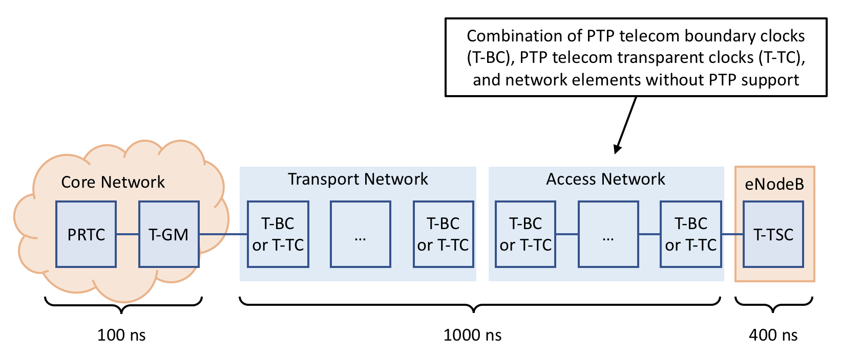
To meet the end-to-end requirement, a loose upper bound on timing error introduced by Terragraph is ±1 µs between the ingress node connected to the POP and egress node connected to the base station. Since TG will be benchmarked against wired backhaul networks, the synchronization accuracy achievable with TG should be as good as possible, and with the approach outlined below Terragraph can transport PTP flows while introducing less than 250 ns of timing uncertainty. Achieving less than 250 ns accuracy leaves at least 750 ns for other network components between the T-GM in the core network and the Terragraph ingress node.
System Architecture
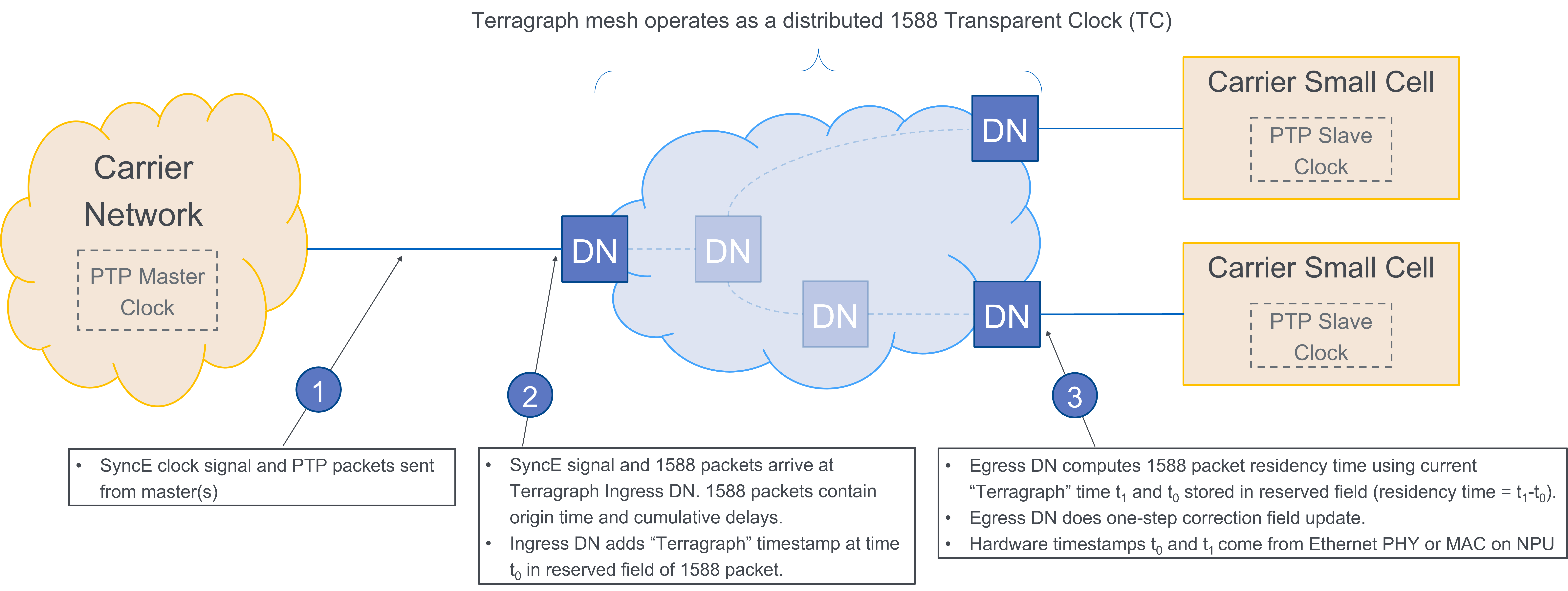
Because Terragraph's TDD (time division duplex) MAC frame structure necessitates a common time reference across TG nodes, the same common time reference can be used to measure the time taken for PTP Sync messages to transit the Terragraph network. PTP provides a mechanism for tracking residence time through a network element and removing it from the packet delay calculation. By using this mechanism PTP packet latency through the TG network can be decoupled from directly impacting protocol performance for timing synchronization.
From a protocol point of view, using a common time-reference to measure transit time through a multi-hop network and updating the correction field in the Sync or Follow Up message can be viewed as a distributed 1588 transparent clock.
Although residence time (transit time through TG) can be removed from the packet delay calculation for timing synchronization as outlined in the section below, G.8273.3 mentions a residence time limit of 10 ms as generally suitable, which should be viewed as an upper bound on maximum latency allowed for PTP packets through TG. For frequency synchronization the requirements in G.8261.1 impose limits on Packet Delay Variation (PDV) for a certain percentage of packets to within ~150 µs.
The ingress timestamp can be propagated from ingress to egress in-band using a reserved field (see details below).
Frequency Syntonization
A PTP transparent clock does not need to maintain a local PTP clock that is synchronized to another PTP clock. Therefore for Terragraph there is no need to explicitly syntonize (frequency sync) the common clock used to measure residence time to a PTP grandmaster clock. In scenarios where tracking clock offset between the TG common clock and the PTP grandmaster may improve accuracy of the residence time calculation (e.g. PTP transport over a GPS-less Terragraph network), the clock offset could be computed in software and used to adjust the residence time calculation accordingly.
Encapsulation and Tunneling
PTP packets sent through the TG network may have various layers of encapsulation or tunneling, and in all cases PTP hardware timestamping must be supported. The timestamping is typically done based on the Start-of-Frame (SOF) delimiter.
According to the standard, PTP packets are encapsulated in any of:
- Ethernet, IPv4, and IPv6
The PTP packets can also be encapsulated in any of:
- L2TP or LT2P over GRE (no encryption enabled/needed)
- MPLS
- IPv6 (including segment routing)
The specific encapsulation used for each MNO should be identified and vetted to ensure HW classification of PTP packets is supported.
DN vs. CN
The NPU used for CN hardware may not support PTP. In scenarios where a CN would normally be deployed but PTP egress is required, DN hardware will be used instead. This may require minor software changes to treat the PTP-enabled DN as a CN (e.g. for scheduling purposes).
Software Requirements
This section describes how PTP packets flow through the Terrragraph network and what functionality is required to implement a distributed end-to-end transparent clock over Terragraph. The goal of an end-to-end transparent clock is to measure packet residence time for PTP event messages and update the correction field accordingly. An E2E-TC can either be a one-step clock or a two-step clock:
- A one-step E2E-TC updates the correction field in event messages (
SyncandDelay_Req) as it egresses on the wire using hardware to perform the update. - A two-step E2E-TC updates the correction field in the corresponding general
message using software to do the update:
- Residence time measured by the E2E-TC for
Syncmessages is used to update the correction field in the correspondingFollow_Upmessage - Residence time measured by the E2E-TC for
Delay_Reqmessages is used to update the correction field in the correspondingDelay_Reqmessage
- Residence time measured by the E2E-TC for
A PTP end-to-end transparent clock does not participate in the best master clock algorithm (BMCA), does not need to maintain a Local PTP Clock synchronized to an external PTP clock, and does not need to do any special handling for most of the PTP general messages. The table below summarizes the action required by Terragraph for each PTP message type.
| Message Name | Message Type | Action Required |
|---|---|---|
Sync | Event | Special handling |
Delay_Req | Event | Special handling |
Follow_Up | General | Special handling only for two-step PTP-TC implementation; otherwise pass through |
Delay_Resp | General | Special handling only for two-step PTP-TC implementation; otherwise pass through |
Pdelay_Req | Event | Peer-delay mechanism not supported |
Pdelay_Resp | Event | Peer-delay mechanism not supported |
Pdelay_Resp_Follow_Up | General | Peer-delay mechanism not supported |
Announce | General | Pass through |
Management | General | Pass through |
Signaling | General | Pass through |
On NXP-based platforms PTP packet processing may be performed by a Linux PTP-TC application running in user space, in AIOP hardware, using DPDK, or some combination of the options. For the discussion below, "Linux PTP-TC application" is used, but that equates to "whatever entity processes/manipulates PTP packets".
For simplicity, the discussion below assumes the PTP clock used for hardware timestamping is synchronized to the Terragraph common clock (e.g. GPS). If a node's PTP clock is syntonized to the Terragraph common clock but has a known non-zero offset, the Linux PTP-TC application needs to account for the offset accordingly. For example, the PTP clock may count "ns since power on", in which case Linux PTP-TC application needs to map "ns since power on" for PTP timestamps to the Terragraph common clock and vice-versa. The same approach could be extended to a node whose PTP clock is not syntonized to the Terragraph common clock if the frequency offset is known and the Linux PTP-TC application can adjust timestamps accordingly. Such adjustments are mentioned below as "if necessary" or "for further study".
PTP Packet Identification
Software must be able to identify when a PTP message enters and leaves the Terragraph network at an ingress/egress node. The most straightforward way is to manually configure nodes as a PTP ingress/egress nodes and consider packets arriving from or heading to the 1G/10G interface on a PTP ingress/egress node as entering or leaving the Terragraph network. This approach allows PTP packets to transit intermediate wired interfaces within the Terragraph network without terminating the transparent clock, which would result in additional timing uncertainty.
Packets must be identified by packet classification as PTP if:
- The 2-byte EtherType matches the value reserved for PTP (0x88F7), or
- UDP port matches PTP reserved port (319 or 320)
Packet classification must be performed after removal of any encapsulation/headers.
Timestamp Insertion
PTP timestamps shall be sent from ingress node to egress node in-band using the
4 bytes at octet 16 of the common message header (Table 18, 1588-2008). This
field is renamed messageTypeSpecific in 1588v3 and using it for this purpose
is explicitly allowed by the latest draft 1588v3 standard (see details
below).
For ingress PTP packets the Linux PTP-TC application is responsible for
converting the hardware PTP timestamp (typically 8 bytes) to a 4-byte timestamp
with ns resolution and placing it in the messageTypeSpecific field.
For egress PTP packets the Linux PTP-TC application is responsible for
converting the 4-byte timestamp contained in the messageTypeSpecific field to
the format expected by the hardware PTP clock for one-step correction field
update (typically 8 bytes) in addition to setting all 4 bytes of the
messageTypeSpecific field to 0.
Packet Flow
This section describes how PTP Event messages flow through the Terragraph
network and includes platform-specific details for NXP LS1048/1088 based
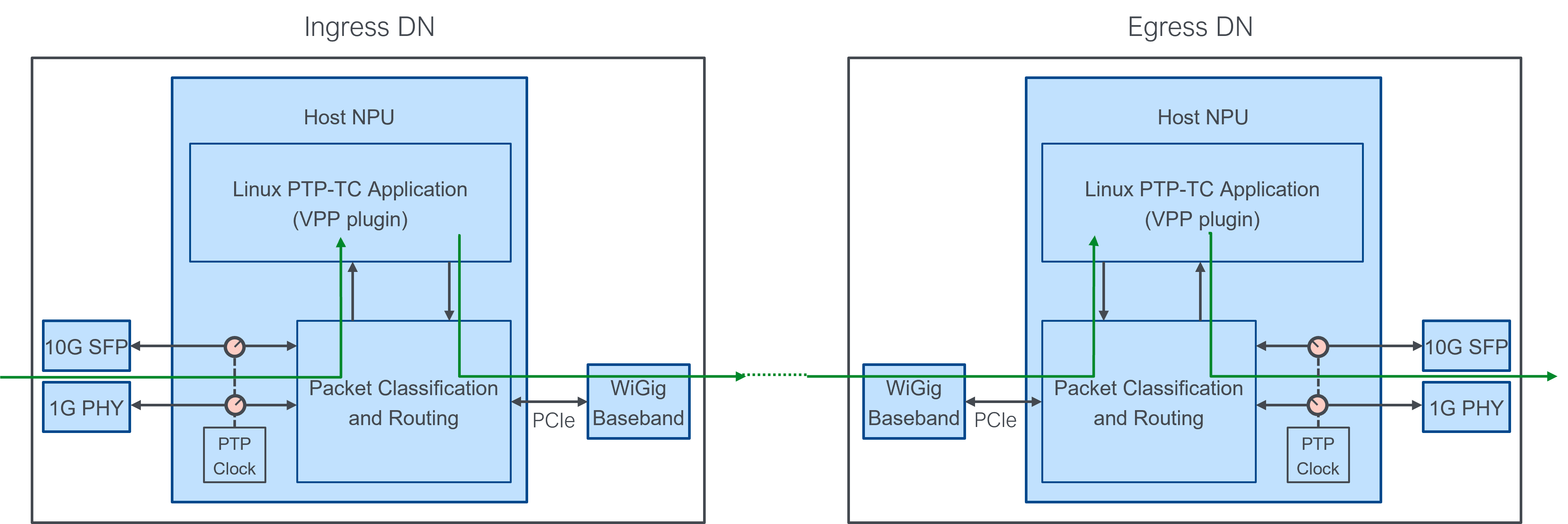
implementations where necessary. The diagram below shows a single PTP message
entering the Terragraph network at an ingress node, going across one or more
wireless hops (not shown), and leaving the Terragraph network at an egress node.
For PTP Sync messages the ingress node is the POP node and the egress node is
the CPE node. For PTP Delay_Req messages the ingress node is the CPE node and
the egress node is the POP node.
The discussion below assumes some PTP packets are processed by a Linux PTP application. Although "fast-path" processing is not strictly required, the functionality can be implemented on the NXP AIOP instead of as a Linux application.
Software Implementation
Terragraph implements a distributed end-to-end one-step transparent clock in two layers, depending on hardware availability:
- NPU (NXP LS1048A) with ~20ns accuracy, implemented on the host in the Linux PTP-TC application.
- 10G PHY (Microsemi VSC8254) with ~1ns accuracy, with hardware timestamping
statically configured through the
malibu_charapplication.
The user must enable timestamping on both the network ingress Ethernet
interfaces and the network egress interfaces via the timingParams node
configuration structure. Note that ingress/egress in this case refers to the
Terragraph network as a whole; distribution nodes or network interfaces that are
internal to the network need only to pass frames along without any special
handling.
In order for delay to be accurately captured between ingress and egress nodes, the clocks of the two systems must be synchronized. The Terragraph driver interface application synchronizes clocks on the NPU and/or 10G PHY at each 1pps strobe as follows:
- NPU via direct DPAA2 register reads/writes to synchronize the NXP PTP hardware clock.
- 10G PHY via a custom datagram socket protocol in
malibu_charto synchronize the VSC LTC (local time counter) clock.
NPU Timestamping
This section discusses the Linux PTP-TC application, a VPP plugin. Refer to VPP Implementation for additional context about VPP.
Configuration
VPP does not process PTP packets by default. The user must enable the ptptc VPP node via the following node configuration fields:
timingParams.PTP_VPP_INTERFACE- The timestamping interface nametimingParams.PTP_VPP_OFFSET_NS- The factory calibration constant (in ns) to compensate for internal timestamping biastimingParams.PTP_VPP_NXP_PORT- The NXP NPU timestamping port number(s), i.e. DPMAC indexes, on which to enable the one-step correction field update in hardware (or 0 to use software timestamping)
Implementation notes
VPP packets are forwarded along a directed graph beginning at input nodes (e.g.
dpdk-input), traversing through one or more internal nodes (e.g.
ip6-lookup), and finally terminating at an output node (e.g.
interface-output). Internal nodes are generally attached to a feature arc: a
list of functions that are called sequentially when processing packets of a
certain type. The Linux PTP-TC application applies associated ingress and egress
packet manipulations based on the direction of the flow of traffic.
The ptptc node is attached to the ip6-unicast feature arc. Thus, it will
inspect any IPv6 unicast packets that arrive at the ingress node to determine
whether they are one of the PTP packet types that is modified. If the packet is
a UDP packet with destination port 319 and has PTP type Sync or Delay_Req,
then the lowest order 32 bits of the current 1588 clock timestamp are stored in
the packet's message_type_specific field.
The ptptc node is also attached to the interface-output feature arc. For PTP
packets arriving at this node, the current timestamp is read from the 1588 clock
and combined with the lower 32 bits from the message_type_specific field added
by the ingress node, thus recreating the original timestamp. The difference
between the current timestamp and the original timestamp goes into the PTP
correctionField, to be consumed by downstream clocks. If requested, the output
node will do the correctionField update using DPAA2 hardware facilities by
setting the original (recovered) timestamp and, in the DPDK driver, copying that
timestamp to the frame annotation area.
DPAA2 details
The Linux PTP-TC application makes use of a number of features in the DPAA2 Wire-Rate I/O Processor (WRIOP) to support low-latency timestamping, summarized below:
- RX timestamping. This is implemented in DPAA2's DPDK driver for all
packets, so nothing specific is required; the driver just needs to set the
PKT_RX_TIMESTAMPoffload flag and copy the timestamp from frame annotation word 2 into therx_timestampdynfield. - TX one-step update. The WRIOP can directly insert the delta between the
current (at time of transmit) 1588 timestamp and the timestamp stored in the
frame annotation area (part of the frame description). To perform the update,
the hardware needs the following settings:
- The PTP bit needs to be set in the frame annotation status (frame annotation word1)
- The original RX timestamp needs to be set in the frame annotation (frame annotation word 2)
- The frame control (FRC) field needs to have the WRIOP and the FASV (frame annotation status valid) bit set
- The DPMAC corresponding to the egress interface must have the
SINGLE_STEPregister configured with the offset of thecorrectionFieldand the enable and checksum bits set appropriately.
- Timing offset and drift correction.
- There are several registers that determine the rate at which the 1588
timer counter (
WRIOP_TMR_CNT_{L/H}) increments:TMR_ADDENDscales the input clock frequency to derive a nominal PTP clock frequencyTMR_PERIOD, part of theTMR_CTRLfield, is the amount by whichTMR_CNTincrements
- By default, the input clock is 700 MHz,
ADDENDis (32-bit fixed-point) 5/7, andPERIODis 2, meaning the nominal clock runs at 500 MHz and the counter counts by two, giving an effective 1 ns period. - To correct the 1588 clock,
TMR_OFFSET_{L/H}is programmed with the fixed difference between the two clocks. - To correct for drift, it is necessary to speed up or slow down the nominal
PTP clock by adjusting
ADDENDa small amount. The target value can be computed as(1e9/(1e9 + drift_ppb)) * original_addend.
- There are several registers that determine the rate at which the 1588
timer counter (
10G PHY Timestamping
This section discusses the malibu_char application used to configure the
Microsemi VSC8254 10G PHY for hardware timestamping. Refer to
Puma MBH Hardware
for specific hardware details.
Configuration
The user must configure the malibu_char application via the following node
configuration fields:
timingParams.PTP_VSC_CTRL_SOCKET- Enable PTP-TC timestamping and use a given control socket path for LTC clock synchronizationtimingParams.PTP_VSC_PORT- The port used for PTP-TC timestamping and ESMC input/output
Implementation notes
The malibu_char application is part of the user-space "MESA" library from
Microchip. It is patched to perform PTP-TC and SyncE initialization at boot
time, and also to run as a daemon with a custom datagram socket protocol for the
purpose of synchronizing the LTC (local time counter) clock. The Terragraph
driver interface application synchronizes the LTC clock (e.g. time-of-day and
frequency adjustments) using this interface.
The datagram socket protocol is documented in
vtss_appl_10g_phy_malibu.c:handle_dgram_sock_msg() from
recipes-utils/vsc8254phy/files/0005-Add-datagram-socket-interface.patch.
Hardware Requirements
The distributed PTP-TC architecture described in this document imposes the following mandatory hardware requirements:
- Hardware timestamping of PTP packets sent or received over any 1G or 10G interface with at least 40 ns accuracy
- PTP timestamping done for all packets with EtherType 0x88F7 or UDP destination port 319 or 320
- Checks for EtherType and UDP destination port are done respecting the structure of standard protocols when determining attributes of the frame (e.g. after removing any encapsulation)
- PTP clock used for timestamping is syntonized to a supported time reference (e.g. GPS, HTSF)
The following can optionally be supported by hardware:
- The NPU can support one-step correction field update to simplify the software requirements for the Linux PTP-TC application
- Timestamping can be done by the external 1G and/or 10G PHY for improved accuracy, but with additional complexity and cost
For NXP based-processors:
- LS1012 does NOT support PTP timestamping in hardware
- LS1023/1026/1041 supports PTP timestamping in hardware for 2-step operation
- LS1048/1088 supports PTP timestamping in hardware for 1-step operation (superset of 2-step hardware support)
Additional Background
PTP delay request/response measurements
PTP uses an exchange of four timestamps between master and slave devices to
propagate frequency and phase/timing information from the master clock to the
slave clock. The master periodically sends Sync messages as unicast or
broadcast messages, depending on the PTP profile.
A single delay request-response procedure is shown in the figure below. The
master sends a Sync message at time t1, which is received at the slave
device at time t2. A 1-step master includes the timestamp t1 in the Sync
message itself, whereas a 2-step master sends a Follow_Up message containing
the timestamp — the protocol accuracy is the same in either case. After
receiving a Sync message the slave sends a Delay_Req to the master at time
t3, which the slave records locally. The master receives the Delay_Req at
time t4 and sends the timestamp to the slave in the Delay_Resp message.

Using the four timestamps determined during the delay request-response procedure, the slave computes the mean path delay and slave clock offset relative to the master clock as:
meanPathDelay = [(t2 – t1) + (t4 – t3)]/2 = [(t2 – t3) + (t4 – t1)]/2
offsetFromMaster = (t2 – t1) – meanPathDelay
If any delay asymmetry in the network is known, PTP includes procedures to correct for it, but unknown or uncompensated delay asymmetry will directly introduce timing error at the slave.
PTP in cellular networks
Using PTP for frequency distribution vs. timing synchronization imposes very different requirements on the network topology, with the latter being much more difficult to achieve.
PTP for frequency distribution
Frequency distribution can be done over a generic network that does not contain PTP-capable elements as long as the packet delay variation (PDV) requirements are met. PTP architectures for frequency distribution and associated performance requirements are given in ITU-T G.826x series specifications.
Packet delay variation (PDV) performance requirements are quantified using the "floor packet percentage" (FPP) metric. FPP is defined as the percent of packets that experience delay within delta µs of the minimum (or floor) packet delay in every fixed interval.
- G.8260 defines the Floor Packet Percentage (FPP) metric
- G.8261.1 defines a network limit for PDV in terms of FPP
- G.8263 defines the input tolerance expected of a 1588v2 frequency slave
For reference, the FPP limits specified in G.8261.1 for a 10 node optical network with a mix of 1 and 10 Gbps links requires that in every 200 second window at least 1% of PTP Event Message packets experience delay within 150 µs of the minimum delay through the network. Achieving this would impose strict QoS requirements on Terragraph for delivering PTP packets across the network.
PTP for timing distribution
In addition to PDV, timing synchronization is impacted by asymmetric delays in the network. Network architectures for PTP-based timing distribution typically assume "full on-path support" (OPS), which means every network element between master and slave clocks is either a PTP boundary clock or PTP transparent clock. ITU-T G.827x specifications cover topologies and performance requirements for PTP-based timing distribution.
- G.8271.1: Network limits
- Allocates 1000 ns timing error to entire packet network
- G.8273: Framework for time and phase synchronization
- G.8273.2: Telecom boundary and slave clocks (T-BC/T-TSC)
- G.8273.3: Telecom transparent clocks (T-TC)
- Control of residence time variation is important to limit the irregular inter-arrival period of the PTP messages received by a telecom boundary clock (T-BC) or by a telecom time slave clock (T-TSC) as this may impact their performance or lead to the generation of alarms
- Considers T-TC syntonized by physical layer frequency synchronization (T-TC syntonized by PTP is for further study)
- G.8275.1: Topologies and PTP profile
An example packet network timing budget from G.8271.1 Table V.1 breaks down as follows:
- 100 ns for PRTC + T-GM
- 1000 ns for packet network broken down as:
- 550 ns cTE (10 class A T-BC/T-TC + 1 T-TSC all @ 50 ns cTE)
- 250 ns uncompensated link asymmetries
- 200 ns random
- 150 ns eNB noise
- 250 ns eNB rearrangement and short holdover
Distributed PTP-TC without GPS at ingress/egress
As mentioned earlier, timing information can be propagated from one TG node to the next with adequate resolution to meet cellular backhaul requirements using 802.1AS and high-resolution time of departure/arrival measurements. 802.1AS makes use of existing 802.11 services to compute round trip latency and time offset:
- Timing Measurement (TM) 802.11v (2011)
- Fine Timing Measurement (FTM) 802.11-2016
For 802.11 links, timestamp accuracy determines the per-link and ultimately end-to-end accuracy; for 802.11ad, in theory, timestamping using a clock frequency of at least 1760 MHz (~0.5 ns) is possible. Current 802.11ad baseband chips are expected to achieve at least ~5 ns accuracy without additional enhancements.
To use the synchronization achieved with TM/FTM as a common time reference for the distributed transparent clock architecture described in this document, timing must be propagated from baseband to the PTP clock used for timestamping. A common 1 PPS signal available to the baseband, NPU, and 1G/10G PHY can be used for this purpose.
Propagating ingress timestamp to egress
Calculating residence time at the egress node requires propagating the ingress timestamp to the egress node. The way in which the ingress timestamp is propagated to the egress node is outside the scope of the PTP standard, but similar functionality is required in many PTP implementations. For example, when timestamping is done by an external PHY it may be difficult to track sideband information about corresponding PTP packets, and for conformance reasons additional bytes cannot be appended to the payload prior to passing it to the MAC. A common approach in such scenarios is to use reserved fields in the PTP message for internal timestamps and to zero-out the field before the message is sent on-the-wire to maintain PTP conformance.
The 1588v3 specification includes a change to explicitly allow the use of a
reserved field in the PTP common header for internal timestamping. The change
renames the 4 bytes at octet 16 of the common message header (Table 18,
1588-2008) to messageTypeSpecific and explicitly leaves its use for PTP Event
messages up to internal implementations (but must be sent as all 0 over the
wire). For Terragraph, the 4 bytes can be used to transfer a 32-bit nanosecond
timestamp derived from the common clock. Rollover must be handled at the egress
and the egress node must zero-out the messageTypeSpecific field before sending
the message on-the-wire.
Synchronous Ethernet
Terminology
- SyncE: Synchronous Ethernet
- ESMC: Ethernet Synchronization Messaging Channel
- PLL: Phase-Locked Loop
- DPLL: Digital Phase-Locked Loop
- NCO: Numerically-Controlled Oscillator
- TSF: Timing Synchronization Function
- HTSF: High Resolution Timing Synchronization Function
Basics
Synchronous Ethernet (SyncE) is an ITU-T standard for transferring a clock signal (frequency reference) over an Ethernet physical layer. SyncE is used extensively in telecom networks for high-accuracy frequency synchronization of cellular base stations to primary time reference clocks located elsewhere in the network. The primary standards are:
- ITU G.8261: SyncE architecture and performance limits (network)
- ITU G.8262: SyncE clock requirements (equipment)
- ITU G.8264: Protocol aspects of Ethernet Synchronization Messaging Channel (ESMC)
- ITU-T G.781: Synchronization state machine
The main difference between a device that supports SyncE and one that does not is that in a device that supports SyncE, the Ethernet PHY is clocked by a stable PLL and is able to extract the frequency of its input signal and pass it to its system clock. Across maximum time and temperature swings SyncE allows a slave clock to maintain synchronization to a reference clock many hops away to less than 100 parts per trillion frequency accuracy when in the locked state.
Although SyncE was designed with (wired) Ethernet interfaces in mind, non-Ethernet based physical transport is also possible. If both ends of a wireless link are viewed as part of a single node, it becomes equivalent to a wired backhaul network element that supports SyncE in from the core and SyncE out to the base station — cellular network operators may expect this capability to be present in cellular backhaul products.
From a protocol perspective, SyncE uses a simple layer 2 messaging channel called the Ethernet Synchronization Messaging Channel (ESMC) to communicate information about synchronization status and accuracy to peer nodes. ESMC information PDU are sent as heartbeat messages once per second as Ethernet slow protocol frames to provide a continuous indication of the clock quality level (QL), which is carried in the ESMC PDU as an SSM code (synchronization status message from SDH). If a node doesn't receive an ESMC information PDU for five seconds it triggers a synchronization state change, and anytime the synchronization state changes a node immediately sends an ESMC event PDU indicating the new QL to peer nodes.
System Architecture
SyncE over Terragraph
The primary technical challenge for SyncE support in Terragraph is frequency distribution over the wireless link. Unlike microwave backhaul products where the hardware architecture looks similar to SyncE over Ethernet media:
- Terragraph air interface is TDD (time division duplex) instead of FDD (frequency division duplex), so continuous frequency transfer is not possible
- Frequency estimation and compensation is done in the digital domain, so even during transmissions there is no analog recovered clock output that could drive a PLL (this is an expected consequence of the packet-based PHY protocol used in Terragraph)
Despite these differences, a Terragraph node can still recover the clock frequency used by its peer node via TSF drift, or using packet TX and RX timestamps to measure, track, and compensate for frame timing drift between nodes over time. The wireless card would periodically determine the phase or frequency between its own clock and its peer clock and communicate the offset to a numerically-controlled oscillator (NCO) on the SyncE PLL.
The Terragraph frame structure is based on TSF timestamps with 1 µs granularity, and these timestamps are already used to synchronize multiple TG nodes over the air. By driving the upstream node's baseband clock from the synchronized SyncE PLL, TSF on the upstream node will stay synchronized with the SyncE reference clock and any TSF drift measured by the downstream node can be attributed to a frequency offset between the local clock and the reference clock. The SyncE PLL can then use periodic measurements of TSF drift to correct the frequency of clock outputs for the 1G/10G SyncE PHYs.
All 802.11ad/ay modems that support fine timing measurements have the hardware capability to generate TX/RX packet timestamps with nanosecond-level accuracy — several orders of magnitude better than 1 µs TSF. Throughout this document support for higher resolution timestamps is referred to as "high resolution TSF" or HTSF. With HTSF accuracy of 15 ns, a 100 ppt frequency offset results in a measurable HTSF drift in only 15e-9/100e-12 = 150 seconds. Assuming the downstream node local clock (TCXO/OCXO) and PLL meet stability requirements for a SyncE reference clock during holdover (e.g. over time, temperature, voltage, and load), HTSF (in conjunction with SyncE TCXO/OCXO and PLL) is sufficient to meet ITU requirements for SyncE transport.
Network View
The block diagram below shows the relationship between the clock reference flow through physical layer components and the corresponding ESMC channel.

Here, a primary reference clock (PRC) in the packet core provides the SyncE reference clock. On the ingress Terragraph DN ("DN1"), the hardware SyncE DPLL recovers the clock from the 10G PHY and uses it as the WiGig baseband clock. The egress Terragraph DN ("DN2") uses the OTA Sync mechanism with high-resolution timestamps and a software PLL to drive the NCO mode clock used for egress to the 10G PHY.
Software Requirements
Software PLL
One of the most complicated aspects of supporting SyncE in Terragraph is the implementation of the slave PLL to lock to and track the reference clock using HTSF phase error measurements. Every BWGD (25.6 ms) heartbeat/keepalive messages between DN nodes will contain the full 64 bit HTSF timestamp with nanosecond resolution. The difference between the slave node's HTSF and peer node's HTSF provides the phase error signal used to drive the phase-locked loop and keep the clocks synchronized. The diagram below shows overall PLL operation on the slave node in the locked state.

This requires the following:
- Message sent every 25.6 ms from baseband to host with latest phase error measurement (needs to be handled in quasi-real time and with high reliability)
- Host application to process phase error measurements at supplied rate according to G.8262 filtering requirements
- NCO word updates (output of loop filter) sent from host to system synchronizer once every 25.6 ms update cycle over I2C interface
ESMC
ESMC support in Terragraph requires software to perform the following actions:
- Handle ESMC heartbeat and event messages on SyncE input ports
- Update sync state according to ESMC messages received
- Generate ESMC messages on SyncE output ports according to current sync state
- Event messages must be generated upon QL change
- Heartbeat messages must be generated at 1-second intervals, only when the QL is not "DNU" (do-not-use)
- The maximum ESMC PDUs transmitted per heartbeat interval shall not exceed 10 (ITU-T G.8264 section 11.3.2.1)
- The destination address shall be set to the Slow Protocol multicast address 0x0180c2000002 (IEEE 802.3 Annex 57B)
Packets must be identified by packet classification as ESMC if:
- The 2-byte EtherType matches the value reserved for Ethernet Slow Protocols (0x8809)
- The 1-byte Slow Protocol subtype matches the value 0x0a
- The 3-byte ITU-OUI matches the value 0x0019a7
- The 2-byte ITU subtype matches the value 0x0001
Note that the implementation supports only ESMC protocol version 1, as provided in the first 3 bits of the "flag" field.
The "best" clock quality level (QL) is determined by the following hierarchy (ITU-T G.781 section 5.4.2.1), from highest to lowest preference:
- PRC, PRTC, ePRTC
- SSU-A
- SSU-B
- EEC1, eEEC
- DNU
Software Implementation
Terragraph implements SyncE using two components:
zl3079xdriver implementing the slave PLL on the Microsemi ZL30795 system synchronizer chip- Linux ESMC application running inside VPP.
The components communicate over
ioctl commands to the /dev/zl3079x miscdevice.
Software PLL
The zl3079x driver is built as a kernel module and loaded during Terragraph
driver initialization. It processes the following messages:
- Northbound: HTSF messages from WiGig firmware (
TG_NB_HTSF_INFO) via Terragraph driver hooktgd_register_htsf_info_handler() - Southbound: PLL register reads/writes via I2C client
The SyncE PLL loop filter is implemented as a PI controller, and is driven by phase error measurements contained in HTSF messages every BWGD (25.6ms). When no messages are received for some timeout period (1 second), e.g. because a WiGig link went down, then PLL state is reset. In the case of multiple basebands, the driver locks to only the baseband instructed by the ESMC application and drops other incoming messages.
The driver registers the miscdevice /dev/zl3079x to enable an ioctl
interface with the ESMC application. It exposes the following calls:
ZL_IOCTL_SET_MODE- Set the DPLL mode, e.g. betweenNCO(0x4) andREFLOCK_SYNCE(0x62)ZL_IOCTL_SET_DEVICE- Switch the WiGig device and reset PLL state, e.g. if best received SSM changesZL_IOCTL_GET_LOCKED- Return whether the the DPLL is in the "locked" output state (1) or not (0)- For
NCOmode (i.e. lock to WiGig interface), lock is inferred after ~10 seconds (390 received HTSF messages) without reaching the timeout period - For
REFLOCK_SYNCEmode (i.e. lock to wired interface), lock is determined by querying the DPLL (i.e. locked toREF3PSyncE input, holdover-ready status)
- For
ESMC
This section discusses the Linux ESMC application, a VPP plugin. Refer to VPP Implementation for additional context about VPP.
Configuration
VPP does not process ESMC packets by default. The user must enable the esmc-input VPP node via the following node configuration fields:
timingParams.ESMC_ENABLED- Enable the ESMC applicationtimingParams.PTP_VSC_PORT- Generate and handle ESMC protocol frames on the corresponding interface (port 0 =TenGigabitEthernet1, port 1 =TenGigabitEthernet0)
Implementation Notes
When enabled, the esmc-input node is registered as the handler for Ethernet
Slow Protocols (ETHERNET_TYPE_SLOW_PROTOCOLS) via
ethernet_register_input_type(). VPP only accepts a single handler for each
EtherType, so any other Slow Protocol handler is overridden (e.g. LACP
protocol handler). Any actions that need to be taken in response to received
ESMC packets (e.g. SSM change) are passed to the esmc-process node, described
below.
The esmc-process node is a VPP "process" node which runs as a separate thread.
It waits for signals from the esmc-input node or otherwise runs every 1
second, which is the required ESMC heartbeat interval. ESMC state update logic
is largely contained within this node's esmc_update() function, which does the
following:
- Finds the current interface with the best SSM
- If necessary, issues PLL mode/device changes via
ioctlcommands - Broadcasts an ESMC frame across all configured output interfaces

Hardware Requirements
In addition to the hardware requirements for PTP, the SyncE architecture described in this document requires a system synchronizer clock chip (with SyncE DPLL). The Terragraph node local clock (TCXO/OCXO) and PLL must meet stability requirements for a SyncE reference clock during holdover (G.8262 Option 1 and Option 2 compliance).