Appendix
Appendix A: Network Design Using Google Earth
Google Earth can be used as a planning tool for initial site design. All map images and data are from Google Earth.
Design steps are listed below:
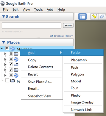
Create a folder to save the network design. Under the "Places" work space area, right-click on My Places, then click Add → Folder. Provide a name for this network design.
Map data ©2015 GoogleIdentify fiber distribution locations (fiber PoP sites).
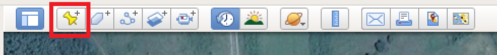
Place the map nearby the first fiber distribution location. Use the "Placemark" tool to add a site to the map. A new window will appear and draw the yellow push pin to the location of the first fiber PoP site. Create a unique site name under the "Name" field.
Map data ©2015 Google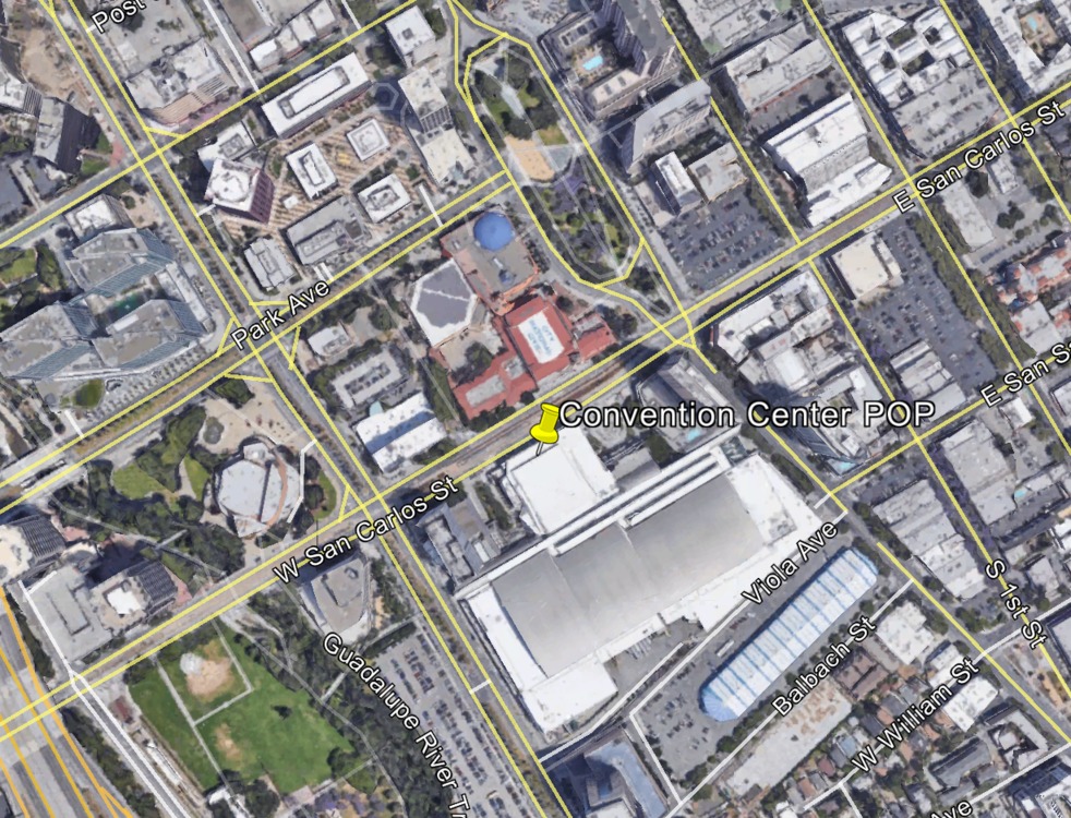
Map data ©2015 GoogleStarting at the fiber PoP, expand the network around the target service area (using the network design criteria described previously). It is best to build the network in a loop topology to allow for network redundancy, starting and ending at the fiber PoP. Use the "Placemark" tool to add each site.
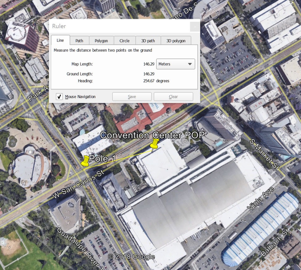
- The distance between sites should range between 25-200 meters, and all links should have clear line-of-sight and avoid any nearby trees or objects which could cause link obstructions. Use the ruler tool to measure the distances of the links.
- Refer to the network design criteria to better understand the implications
of link distance and angles on network performance.

Create a "Placemark" one hop away from the fiber PoP. Give this site a unique name.
Map data ©2015 GoogleConnect each site by using the "Path" tool to draw a line between both locations. The color and weight of the line created by the "Path" tool can be customized.

Map data ©2015 Google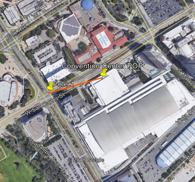
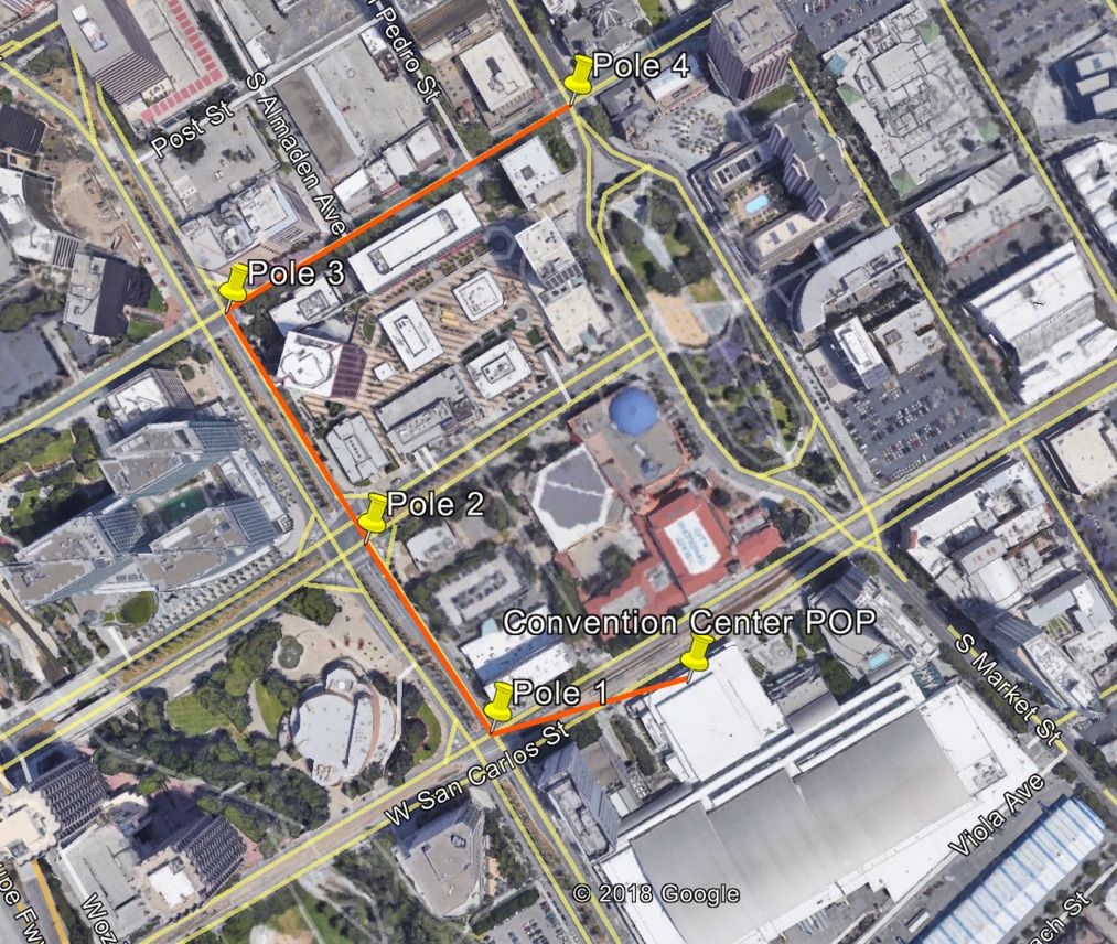
Map data ©2015 GoogleExpand the network outwards one hop at a time — remembering to attempt creation of a loop topology.
Map data ©2015 Google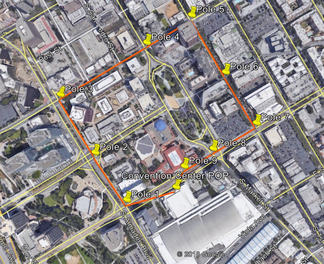
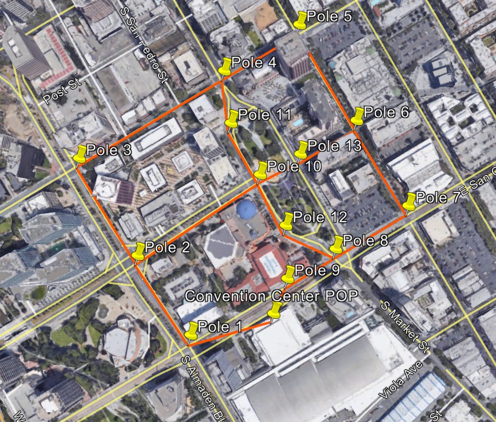
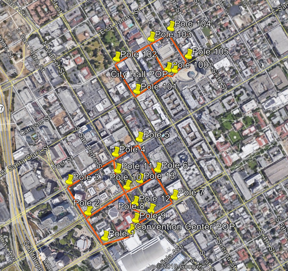
Map data ©2015 GoogleOnce the initial loop topology is designed, find ways to interconnect links to create smaller and larger loops within the service area. This will turn the loop topology into a mesh topology, which allows Terragraph to offer better network performance and reliability. Find new poles or rooftops to build out the mesh topology and then use the "Placemark" and "Path" tools to create the design.
Map data ©2015 GoogleIf there is another fiber distribution location, repeat the steps above for the next target service area. An example with two fiber PoP sites is shown below.
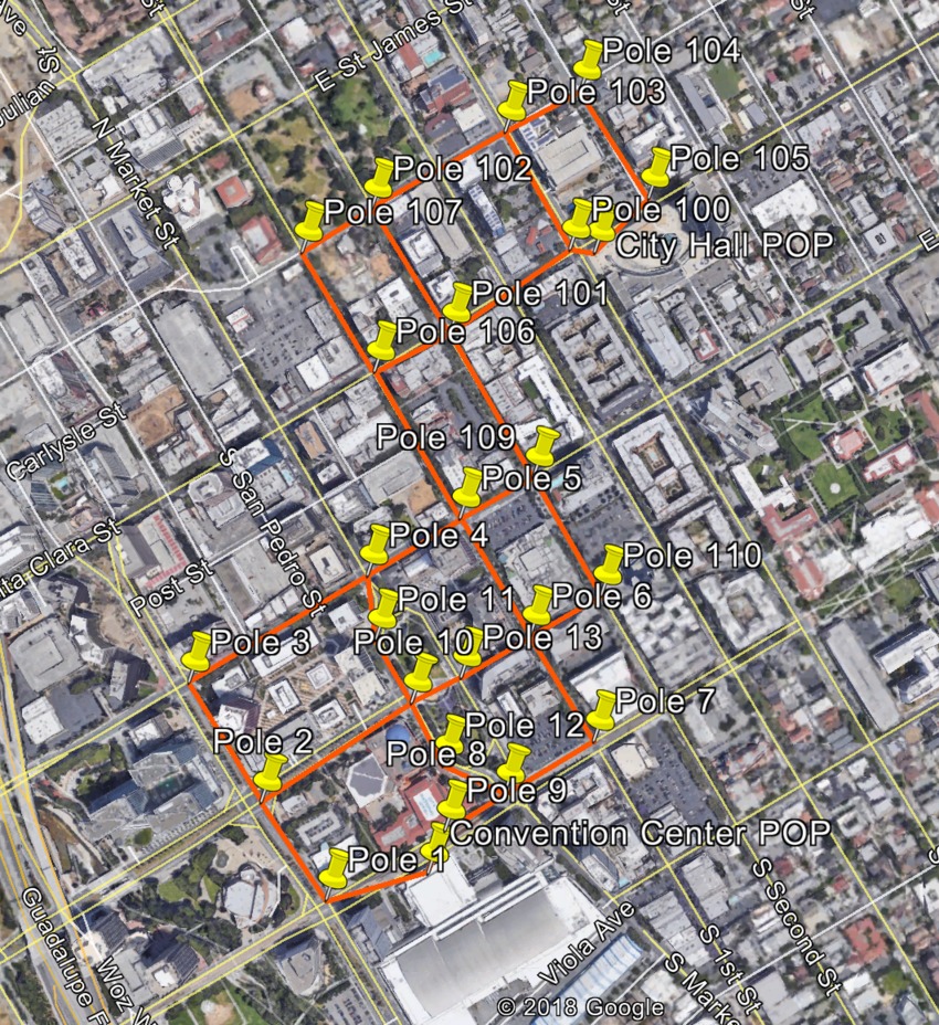
Map data ©2015 GoogleOnce the mesh topologies have been designed for all the fiber distribution locations, it is important to interconnect the smaller individual mesh topologies to build a large mesh topology. This step is important as it allows the network to continue functioning if a fiber PoP fails. Find new poles or rooftops to build out the larger mesh topology and then use the "Placemark" and "Path" tools to create the larger interconnected mesh topology.
Map data ©2015 GoogleWhen the network design is finalized, save the design. Right-click on the folder that was created in the first step, then click Save Place As... to export the design as a Google Earth KMZ file.
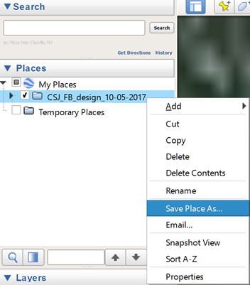
Map data ©2015 Google