Beamforming and Link Adaptation
Beamforming (BF) is the process of using signal propagation information between two antennas and modifying antenna characteristics to maximize the signal quality between those antennas. The BF process accomplishes this in a few discrete states, including passive acquisition, active signaling, and continuous refinement.
This document describes the Terragraph beamforming procedures, messages, and other information related to the beamforming process.
The Glossary collects the acronyms and defines the terms used in this document.
Link States and Transitions
A link represents the directional connectivity between a transmitter and a receiver. The transmitter and receiver shall independently maintain the state of the link. Conditions can exist where the state of a link as determined by the transmitter differs from the state of the link as determined by the receiver.
There are five link states: Link Down, Link Unstable, Link Acquisition, Link Up, and Link Up with Simultaneous Reacquisition. Figure 1 illustrates these states and the transitions between them. This link state machine exists independently for each link of a node.
![]()
Figure 1, Link States and Transitions
A link enters into a Link Acquisition state when an existing node in the network and a new node perform the BF acquisition procedure to establish connectivity with the network. After successful BF acquisition and association, the link moves to the Link Up state. In the Link Up state, the node monitors the link periodically and takes actions at the link level to operate the link at the maximum throughput (link adaptation).
From the steady state, the node moves the link to the Link Unstable state, whenever there is a packet error burst. In the Link Unstable state, the node takes actions to resolve the error burst. The actions taken to attempt resolution of the error burst include link adaptation, beam refinement, and beam switching. Upon successful resolution, the link moves back to Link Up state.
If the node is unable to resolve the issue causing the link to be in the Link Unstable state within the time allowed, the node moves the link to the Link Down state. In the Link Down state, the node attempts several procedures to revive the link. If the attempts are successful, the node moves the link back to the Link Up state.
If the attempts to revive the link are not successful, the node moves the link to the Link Acquisition state or the Link Down state. If the node is a DN, the link moves to the Link Down state and the node waits for direction from the E2E controller. If the node is a CN, the link moves to the Link Acquisition state.
Table 1 summarizes the procedures associated with each link state and the purpose of those procedures.
| Link State | Procedures | Purpose |
|---|---|---|
| Link Acquisition | Beamforming acquisition | Establish the link and determine a list of micro-routes |
| Link Up | 1. Link adaptation | 1. MCS adjustment |
| 2. Micro-route order update | 2. Micro-route order update (micro-route switching) | |
| 3. Beamforming reacquisition | 3. Micro-route update (detect new micro-routes and remove nonexisting micro-routes | |
| Link Up with Simultaneous Reacquisition | Beamforming reacquisition | Find list of micro-routes from neighboring nodes to perform interference management |
| Link Unstable | 1. Link adaptation | 1. MCS and transmit power adjustment |
| 2. Micro-route update | 2. Micro-route order update (micro-route switching) | |
| 3. DN handoff | ||
| Link Down | 1. Unilateral beam switching (Basic) | 1. Change to an existing backup micro-route |
| 2. Transmit and receive mini-sweep (advanced) | 2. Find an existing micro-route | |
| 3. DN handoff | 3. Change to an existing micro-route with a micro-route with a different DN | |
| 4. Beamforming reacquisition | 4. Acquire new micro-routes |
Table 1, Link States and Procedures
Link Down State
This is the initial state for the link. A node initializes the link information and transitions to the Link Acquisition state as a responder.
Link Acquisition State
A CN always performs the responder role during beamforming procedures in this state. A DN enters the link acquisition state upon link initialization or when directed by the E2E controller while in the Link Down state. The DN always performs the responder role when entering the link acquisition state after link initialization. The DN performs the initiator role only when directed to enter this state by the E2E controller. After successfully completing the beamforming acquisition procedure and association with the neighboring node, the link transitions to the Link Up state.
Link Up State
In this state, both DN and CN monitor the link quality for variations causing decreased signal quality or increased packet error rate. Based on the variation of signal quality or packet error rate, the node performs link adaptation or micro-route reordering. Periodically, the node performs beamforming reacquisition. On direction of the E2E controller, the node transitions to the Link Up with Simultaneous Reacquisition state. On detection of a packet error burst exceeding a preset error threshold for which link adaptation or micro-route, reordering is unable to correct, the node transitions to the Link Unstable state.
Link Up with Simultaneous Reacquisition State
In this state, the node performs beamforming reacquisition under the direction of the E2E controller. After completing the beamforming procedure, including the exchange of new micro-route ordering, the node transitions to the Link Up state.
Link Unstable State
In this state, the node attempts to recover from rapid, dramatic increases in packet error rate. If the node successfully completes the beamforming acquisition procedure, the node exchanges micro-routes and transitions to the Link Up state. If the node does not successfully complete the beamforming acquisition procedure, the node transitions to the Link Down state.
Beamforming Procedures
The Terragraph MAC performs all beamforming procedures using the frames defined in the MAC & PHY Specification. The following defines the beamforming procedures.
- Beamforming Acquisition – discovery and establishment of all possible link level connections (LLC, also referred to as "micro-routes") between any two nodes in the network
- Beamforming Re-acquisition – repopulation of the 2D LLC used for routing on Layer 3 (L3); triggers periodically in the steady state, upon transition to a catastrophic failure state, or add new node states
- Beamforming Refinement – fine adjustments to beamforming weights in the steady state to maximize link quality based on a pre-established 2D LLC
- Micro-route Update – changing the prioritized list of micro-routes in steady state based on changes in link quality and packet error rate
- Link Adaptation – changing the modulation and coding scheme (MCS) and or transmit power to react to varying link conditions
Beamforming Acquisition and Reacquisition
The beamforming acquisition and reacquisition procedures use MAC frame exchanges between an initiator node and a responder node. The beamforming acquisition and beamforming reacquisition procedures share similar workflows. This section describes both of these procedures. Beamforming acquisition operates using either the synchronous sweep or the asynchronous sweep at the responder. Beamforming reacquisition operates only using the synchronous sweep.
Asynchronous Beamforming Sweep
A node shall use an asynchronous sweep when the frame and slot boundary timing is unknown. This condition can exist when a node has not yet received synchronization information or when a link moves to the Link Down state and previously acquired synchronization information has become stale. The purpose of the asynchronous sweep is to establish initial communication between an initiator node and responder node, as well as to synchronize the timing of the responder node to that of the initiator node. Figure 2 shows the Asynchronous sweep procedure.
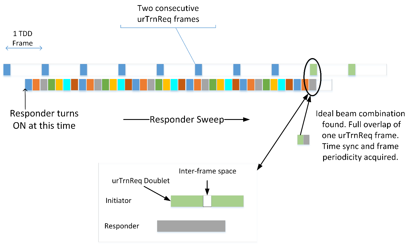
Figure 2, Asynchronous Sweep
When an initiator node attempts to perform beamforming acquisition or
reacquisition with a node with which it has not yet established synchrony or
with which the synchronization information has become stale, the initiator shall
transmit two consecutive urTrnReq frames, separated by the minimum interframe
gap, in each TDD frame. The two consecutive urTrnReq frames are a urTrnReq
frame doublet. The initiator shall sweep through all of the transmit beams,
repeating the same transmit beam index for N-1 repetitions (31 or 61 for the
current implementation) of the two consecutive urTrnReq frames (2N urTrnReq
frames with the same transmit beam index). After the N-1*st repetition, the
initiator shall move to the next transmit beam index. The purpose of this is to
provide the responder node the maximum likelihood of correctly receiving and
decoding one of the urTrnReq frames.
The responder node, when it has not established synchrony with an initiator
node, shall sweep its receiver through every receive beam, dwelling on each
receive beam for a period of time equal to the minimum interframe time plus
twice the time to transmit the urTrnReq frame. At the end of the dwell time on
a receive beam, the responder shall continue to the next receive beam. The
responder shall loop through all receive beams, until successfully receiving and
decoding the urTrnReq frame.
Upon receipt of the urTrnReq frame, the responder shall synchronize its local
time, frame boundary and slot boundary to that of the initiator. After the
responder synchronizes with the initiator, the responder shall terminate the
asynchronous sweep and begin the synchronous sweep.
Synchronous Beamforming Sweep
Synchronous beamforming acquisition and reacquisition are the processes of exchanging frames between an initiator node and a responder node, exhaustively attempting to find pairs of transmit beams from the initiator and receive beams from the responder that allow reliable communication between the two nodes to occur. A node shall use synchronous beamforming acquisition or reacquisition only when the responder node synchronizes to the frame and slot boundaries of the initiator node.
The acquisition and re-acquisition procedures involve testing N_i transmit and N_r receive beam combinations. Figure 3 illustrates this procedure. The procedure assumes link reciprocity. The initiator and responder shall send all frames in the control slot, the first slot, of a frame.
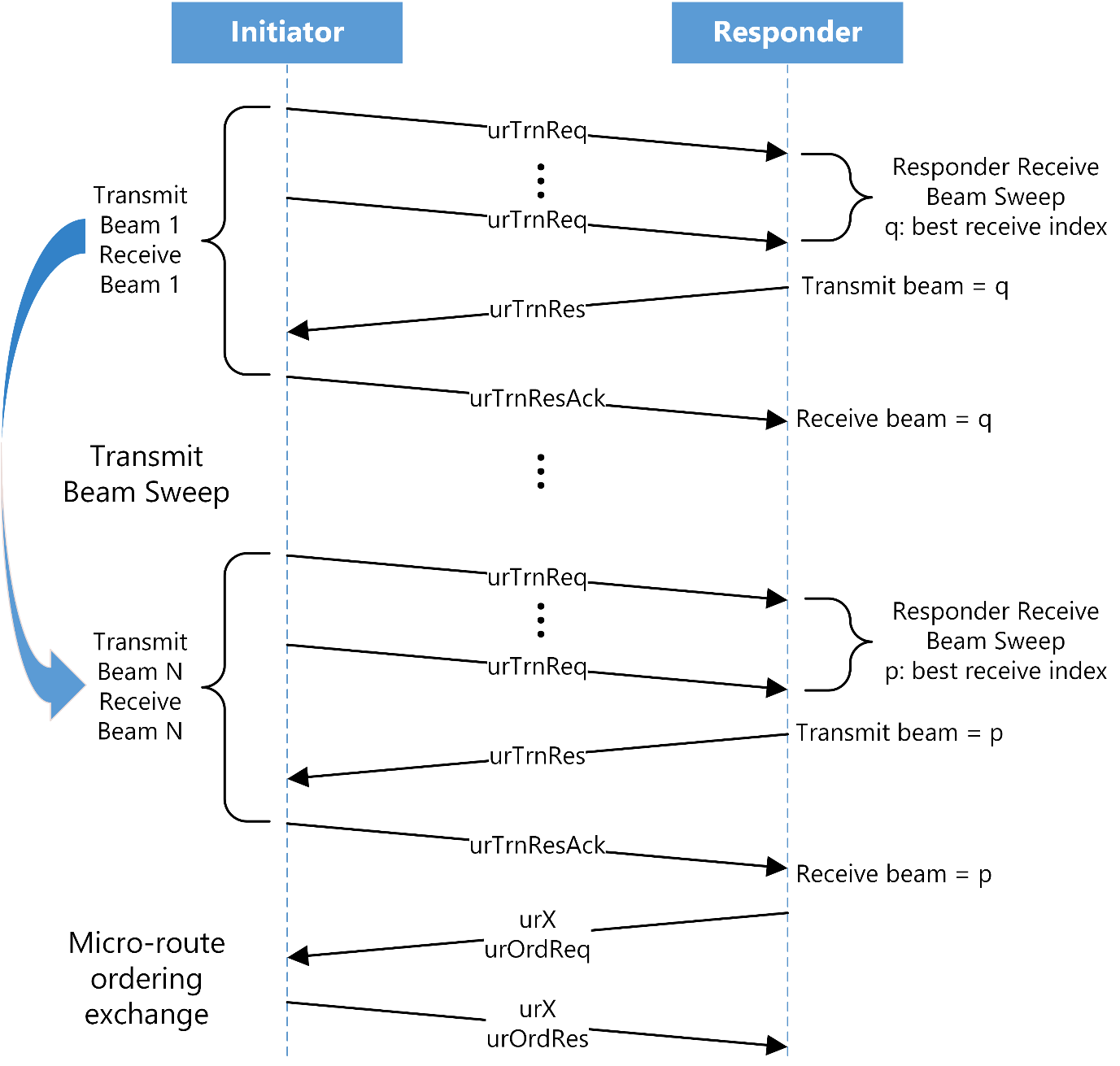
Figure 3, Beamforming Training Flow Diagram
Initiator Operation
The initiator shall transmit two Beamforming Training Request (urTrnReq)
frames with a particular transmit beam index, separated by the minimum
interframe time (a urTrnReq doublet) to begin the procedure. The initiator
shall transmit the doublets in the first slot of the transmit subframe of each
frame. The initiator shall reserve the slots used to transmit the urTrnReq and
receive the urTrnRes frames in the slot maps exchanged with all other
associated nodes.
The initiator shall transmit the urTrnReq doublet for 31 consecutive TDD
frames. The value of FrmNumInBfWin in the urTrnReq frame indicates the
number of transmissions, minus 1. The initiator shall repeat the transmission of
the 31 urTrnReq doublets N times, with each repetition using a new transmit
beam index. The N repetitions allow the receiver to test all possible receive
beam indexes against that transmit beam index.
Fifteen TDD frames after the transmission of the last of the 31 urTrnReq
doublets for a transmit beam index, the initiator shall set the node's receive
beam index to the value of the transmit beam index of the previously transmitted
urTrnReq doublets. This allows the initiator to receive any urTrnRes frame
returned from a responder.
Upon receipt of the urTrnRes frame, the initiator shall populate its 2D LLC
matrix for the corresponding transmit beam with the values returned by the
responder in the urTrnRes and shall send a Beamforming Training Response ACK
frame (urTrnResAck) using the transmit beam indicated as the TxBeamIdx of
the received urTrnRes frame. The initiator shall transmit the urTrnResAck 15
TDD frames after the receipt of the urTrnRes frame. If the initiator does not
receive the urTrnRes from the responder, the initiator shall not send the
urTrnResAck and shall populate its 2D LLC matrix with values indicating a lack
of response from the responder for the corresponding transmit beam.
The number of transmit beam indexes may differ between the beamforming acquisition procedure and the beamforming reacquisition procedure. The beamforming acquisition procedures shall use all possible transmit beam indexes. The beamforming reacquisition procedure may use a subset of all of the transmit beam indexes.
The initiator shall increment the transmit beam index and repeat the exchange of
urTrnReq, urTrnRes, and urTrnResAck frames for each transmit beam index,
until all indexes for the relevant procedure have been attempted. Because a
responder synchronizes with the initiator at a random point during the
initiator's transmission of the urTrnReq doublets for the first transmit beam
for which the initiator receives the urTrnRes, the initiator shall repeat the
31 transmissions of the urTrnReq doublets for that same transmit beam after
completing the synchronous sweep for all other transmit beam indexes.
During the transmissions of the urTrnReq doublets with the final transmit beam
index of the sweep, the initiator shall set the EndTrnFlag in the frame to
indicate to the responder that this is the final set of transmit beam doublets.
Responder Operation
The responder shall listen for urTrnReq frames in the first slot of the receive
subframe of each frame, noting the value of FrmNumInBfWin that indicates the
number of urTrnReq doublets transmitted with the same transmit beam index.
Fifteen TDD frames after the time at which the last urTrnReq frame was
transmitted, the responder shall send a Beamforming Training Response
(urTrnRes) frame, indicating the index of the transmit beam of the initiator
and the indexes and link quality of the receive beams for which the urTrnReq
frame was successfully decoded.
The responder shall send the urTrnRes frame using as the transmit beam the
beam index that has the greatest link quality indicated in the urTrnRes frame.
The responder shall send the urTrnRes frame in the first slot of the transmit
subframe.
The responder shall also track the value of FrmNumInBfWin, indicating how many
urTrnReq frame doublets the initiator transmitted with the same transmit beam
index. The responder shall send the urTrnRes frame 15 TDD frames after
synchronizing with the initiator and after the FrmNumInBfWin indicates the
last urTrnReq doublet with the same transmit beam index.
Upon receipt of the urTrnResAck frame, the responder shall populate its 2D LLC
matrix with the values from its sweep for the corresponding initiator transmit
beam. If the responder does not receive the urTrnResAck, it shall populate its
2D LLC matrix for the corresponding initiator transmit beam with a value
indicating a lack of response from the initiator.
Combined Initiator and Responder Operation
When synchronized to the frame and slot boundaries of the initiator node, the responder node shall use the synchronous sweep, as described in Synchronous Beamforming Sweep. Figure 4 shows the combined operation of the initiator and responder during the synchronous sweep procedure.
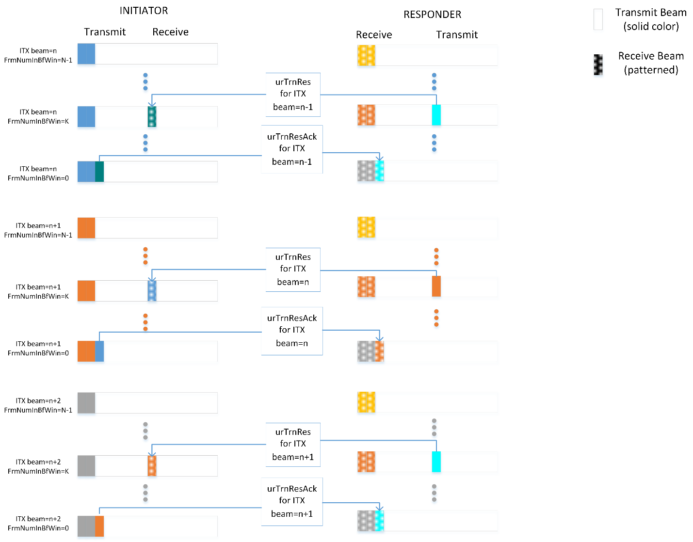
Figure 4, Synchronous Sweep
Micro-route Ordering Exchange
During the synchronous sweep exchanges, the initiator shall order the eight best initiator transmit and responder receive beams, while the responder shall order the eight best responder transmit and initiator receive beams, from the information obtained during the synchronous sweep.
Upon completion of the synchronous sweep exchanges for all transmit beam
indexes, the responder shall send a Beamforming Micro-route Exchange (urX)
frame with the Beamforming Order Request (urOrdReq), listing the eight best
pairs of responder transmit and initiator receive beam indexes obtained from the
synchronous sweep. The responder shall send the urX frame in the first
available control slot to the initiator. The responder shall send this frame
using the transmit beam for which the initiator has indicated the best link
quality in any urTrnResAck frame. The responder shall send the urX frame in
the next available control slot.
After transmitting the urX frame with urOrdReq, the responder shall listen
for the urX frame from the initiator in the first available receive control
slot from the initiator using the receive beam index for which it has indicated
the best link quality in any urTrnRes frame.
Upon receipt of the urX frame from the responder, the initiator shall send the
urX frame with the Beamforming Order Response (urOrdRes), listing the eight
best pairs of initiator transmit and responder receive beam indexes obtained
from the synchronous sweep. The initiator shall send this frame using the
transmit beam for which it has received the best link quality indication in any
urTrnRes frame from the initiator. The initiator shall send the urX frame in
the first available control slot to the responder.
Figure 5 shows the end of the synchronous sweep and the micro-route exchange.
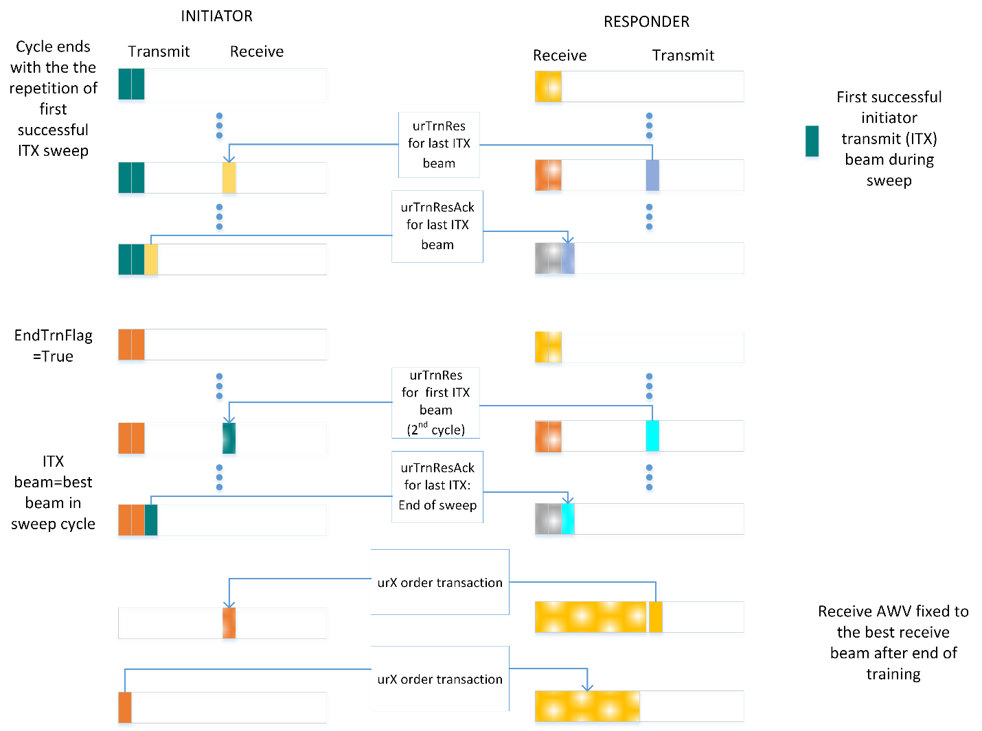
Figure 5, End of Synchronous Sweep and Micro-route Ordering Exchange
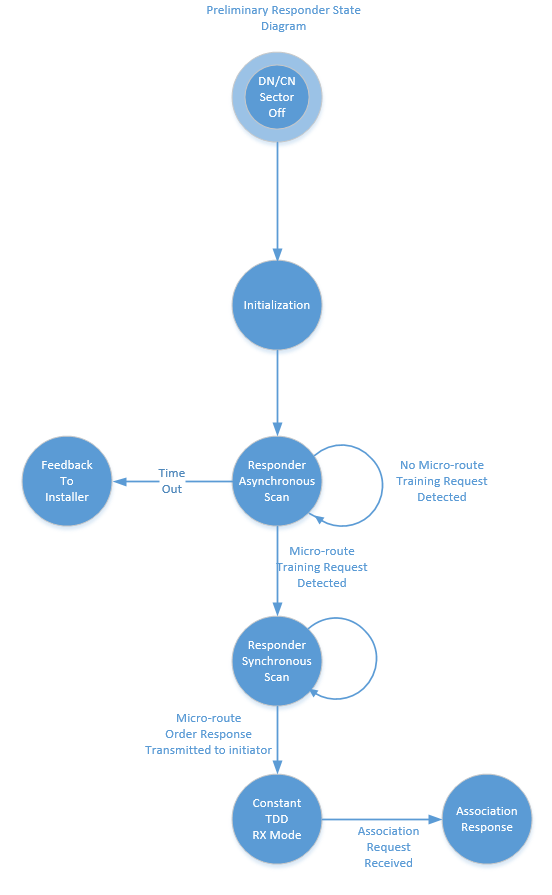
Preliminary Responder State Diagram
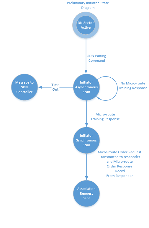
Preliminary Initiator State Diagram
Periodic Beamforming Scan
The periodic beamforming scan (PBS) acquires fresh information about the micro-routes between a single transmitter and a single receiver.
PBS Procedure
The E2E controller shall initiate the PBS by sending Scan Request Messages to the transmitter/receiver node pair selected to perform the scan, called the measurement set. Different from beamforming acquisition, PBS uniquely identifies the transmitter and receiver to each other by their individual MAC addresses and can indicate a subset of the micro-routes for scanning.
The MAC shall start the PBS at a bandwidth grant duration (BWGD) boundary indicated in the Scan Request message. The duration of a PBS varies, dependent on the number of beams scanned. This duration can be less than or greater than a single BWGD.
For the duration of the scan, called the Beamforming Training Duration (BFTD),
the transmitter shall communicate slots reserved for beamforming to all
associated nodes in the normal slot map exchange. The transmitter shall send
urTrnReq training frames (see
MAC & PHY Specification for frame details) for the
PBS only in the first transmit slot of each frame for the BFTD. The receiver
shall attempt to receive the transmitted training frames in the corresponding
receive slot.
The PBS proceeds unidirectionally, from the transmitter to the receiver. Unlike
synchronous beamforming, there is no exchange of urTrnRes or urTrnResAck
frames between the transmitter and receiver and no exchange of micro-routes,
urX frames, at the conclusion of the scan. The receiver sends feedback on the
scan to the controller, when the scan is complete, using the Scan Response
Message.
Figure 6 illustrates the PBS messaging exchange.
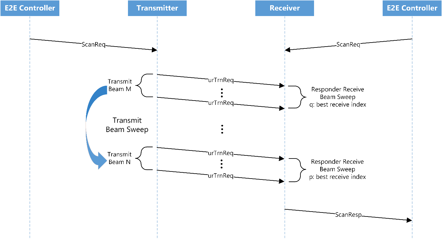
Figure 6, PBS Message Exchange
PBS Scheduling
A scan of the beams selected for a PBS has a duration BFTD. The BFTD derives from the number of transmit beams, the number of receive beams, and the BWGD.
The node shall calculate BFTD, in BWGDs, as shown in Equation 1.
Equation 1, Calculation of BTFD
where N_t is the number of transmit beams, N_r is the number of receive beams, N_f is the number of frames in a superframe, and N_s is the number of superframes in a BWGD. Figure 7 illustrates the calculation of the BFTD.
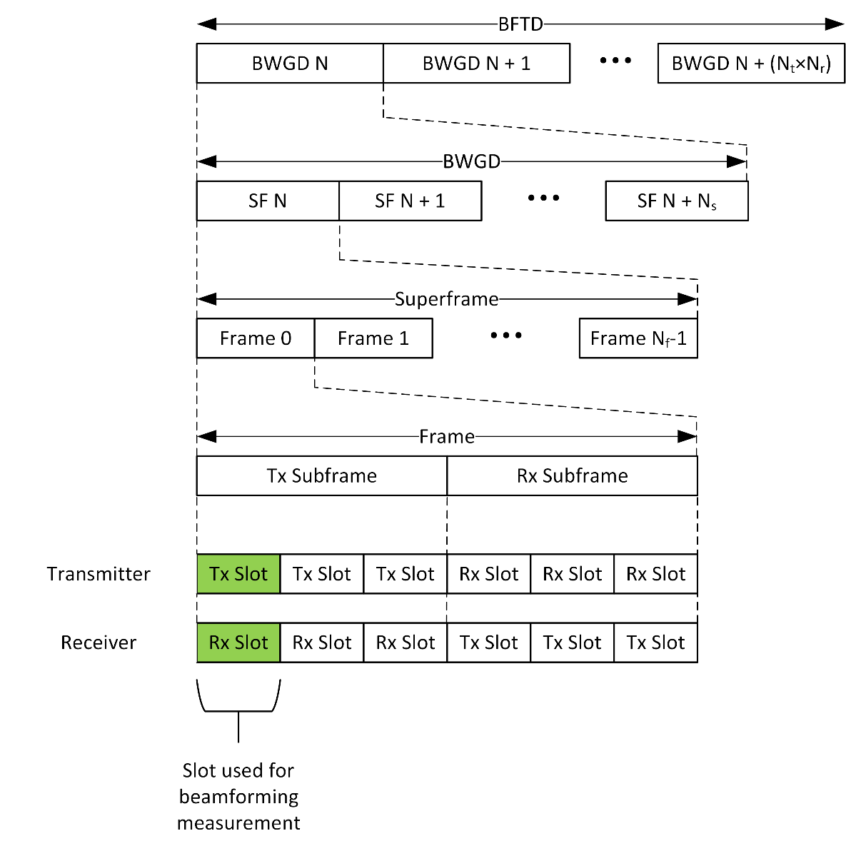
Figure 7, Beamforming Training Duration
The E2E controller shall schedule PBSs such that the duration of an individual scan is significantly shorter than the period of the scans.
Interference Measurement Scan
The interference measurement scan (IMS) uses the PBS mechanism with additional receivers to determine the interference caused by the transmissions of one sector on other sectors. The E2E controller directs each IMS between one transmit sector and one or more receive sectors in close geographic and/or angular proximity. The sectors involved in an IMS do not necessarily have link level connectivity. The sectors selected for the scan called, collectively, the measurement set, perform the scan as directed by the E2E controller and report the results back to the controller.
IMS Procedure
The E2E controller shall initiate an IMS by sending Scan Request Messages to the transmitter node and receive nodes in the measurement set. When the measurement set includes one or more CNs, the controller also shall send Scan Request Messages to the DNs with which the CNs are associated. The nodes in the measurement set shall start the IMS at the BWGD indicated in the Scan Request Message. Each of the nodes in the measurement set will receive or create slot maps reserving slots for beamforming, during which the nodes perform the IMS. The IMS shall proceed as described in PBS Procedure.
For the duration of the BFTD, the DNs in the measurement set shall communicate
slots reserved for beamforming to all associated nodes in the normal slot map
exchange. The transmitter shall send urTrnReq training frames (see
MAC & PHY Specification for frame details) for the
IMS only in the first transmit slot of each frame for the BFTD. The urTrnReq
frames shall use the broadcast address as the destination address of the frame.
The receivers shall attempt to receive the transmitted training frames in the
corresponding receive slot.
The IMS proceeds unidirectionally, from the transmitter to the receivers. Unlike
synchronous beamforming, there is no exchange of urTrnRes or urTrnResAck
frames between the transmitter and receivers and no exchange of micro-routes,
urX frames, at the conclusion of the scan. The receivers send feedback on the
scan to the controller, when the scan is complete, using the Scan Response
Message.
Figure 8 illustrates the IMS messaging exchange.
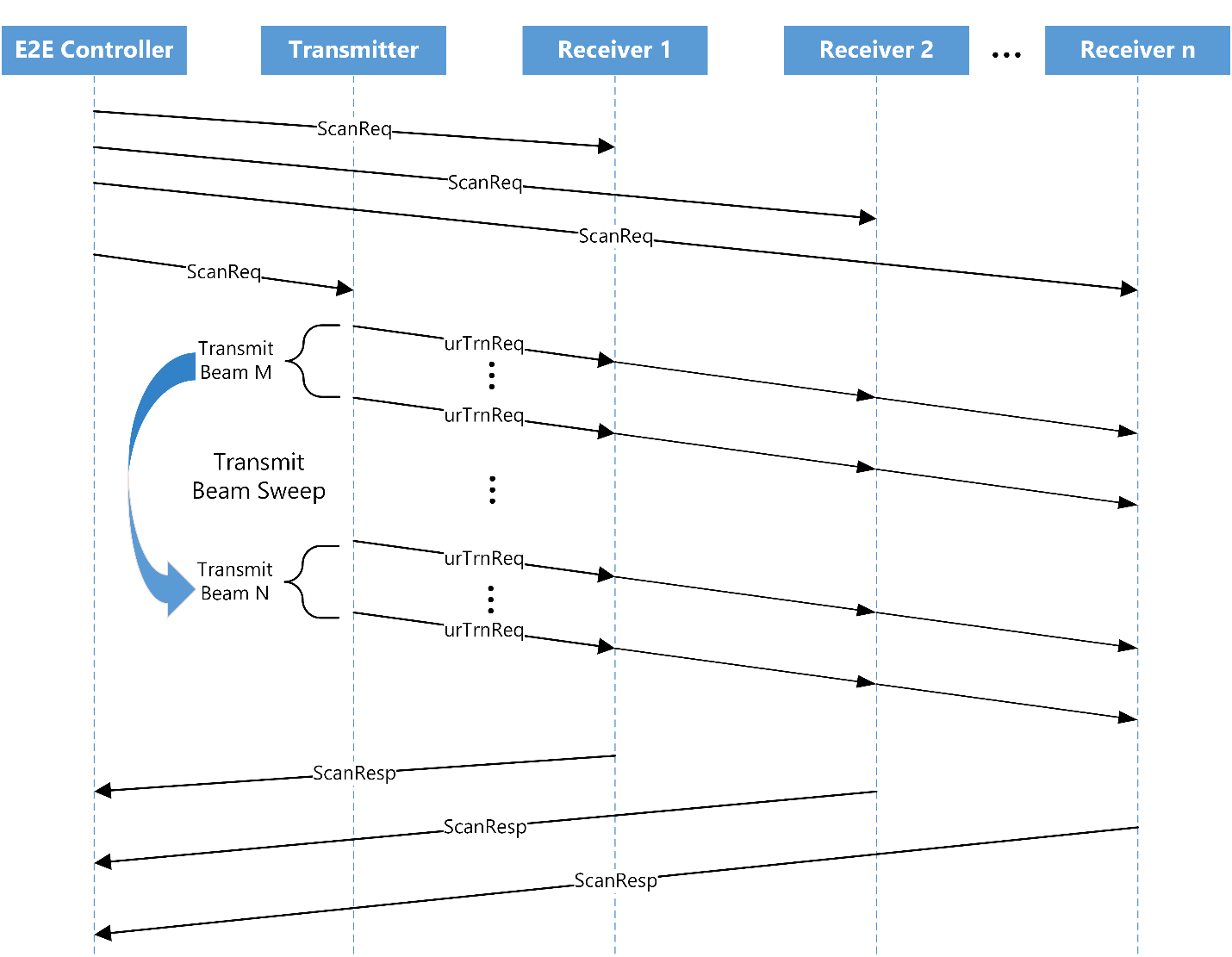
Figure 8, Interference Measurement Scan Message
IMS Scheduling at the MAC
The node shall schedule the IMS as specified in PBS Scheduling.
Scheduling Scans at the Network Level
Individual PBS and IMS operations present little difficulty to schedule in an operational network, as they consume relatively small amounts of bandwidth over short periods. In a large network, however, it can be necessary to schedule several scans to be operating at the same time. In order not to have one scan interfere with another, it is necessary that a sector participate in only one scan at a time; that is, a sector can be a member of only one measurement set for which a scan is taking place. To facilitate the scheduling of parallel scans in a network, the controller determines a sector adjacency matrix, a list of measurement sets, and a scheduling exclusion matrix.
Sector Adjacency Matrix
The controller shall compute a sector adjacency matrix, where the elements in
the matrix indicate the possibility of the sectors interfering with one another.
The sector adjacency matrix is a square matrix with the dimensions equal to the
number of sectors in the network. Each element of the matrix,
sector_adjacency_matrix(i,j), holds a binary value indicating that the sector
i is adjacent to sector j, in the sense that the sectors could cause
interference to one another. The controller can populate this matrix
conservatively, initially, based on deployment measurements of distance, angle,
and obstructions between sectors. As the controller conducts PBS and IMS, the
controller can prune the adjacencies from the matrix based on these
measurements.
Measurement Set Determination
The controller determines a list measurement sets from the sector adjacency matrix. Each element of the measurement set list holds the sectors of a unique row of the sector adjacency matrix. The controller ignores duplicate rows of the sector adjacency matrix, as they would produce a measurement set identical to that derived from the row duplicated.
Scheduling Exclusion Matrix
The controller shall compute a scheduling exclusion matrix, where the elements
of the matrix indicate whether two measurement sets contain any sectors in
common. The scheduling exclusion matrix is a square matrix with the dimensions
of the total number of measurement sets in the network. Each element of the
matrix, scheduling_exclusion_matrix(i,j) = scheduling_exclusion_matrix(j,i)
holds a binary value indicating that measurement set i contains at least one
sector in common with measurement set j.
Scheduling Identifiers
The controller creates a set of scheduling identifiers and assigns one or more measurement sets to the identifier, such that all of the measurement sets with the same scheduling identifier can conduct scans simultaneously. The controller assigns scheduling identifiers to measurement sets using a graph vertex coloring algorithm, where the vertices of the graph correspond to an individual measurement set and the edges between vertices correspond to a scheduling exclusion indicated in the scheduling exclusion matrix.
Link Adaptation Procedure
The link adaptation procedure provides a method for a node to adjust the MCS and transmit power of a link to maximize the throughput of that link.
If the link adaptation procedure is enabled and the control parameters for link adaptation have been configured, a node shall perform the link adaptation procedure for each of its links, while in the Link Up state. Out of band management currently enables and configures the link adaptation procedure.
Receiver Operation
The node shall measure the signal-to-noise ratio (SNR) of all received data frames from each transmitter on a link. The node shall measure the received SNR per transmitter over a minimum period of three superframes. The node shall filter the received SNR per transmitter as shown in Equations 2, 3, and 4 to create a set of link adaptation feedback parameters.
Equation 2, Average Short Term Feedback SNR
Equation 3, Average Post SNR
Equation 4, Average Received Signal Strength Indication
The node shall send the link adaptation feedback parameters to the transmitter in the Heartbeat, Keep Alive, and/or Uplink Bandwidth Request frames, as appropriate for the types of node at each end of the link.
Transmitter Operation
A node receiving the link adaptation feedback parameters may filter the parameters to reduce instantaneous variability. The receiving node shall use the link adaptation feedback parameters to choose a new MCS and/or transmit power level, should the parameters indicate that a change is necessary to improve the link throughput with the node sending the feedback parameters. The node also may modify the choice of a new MCS and/or transmit power level using local measurements of successful and unsuccessful frame transmissions, that is the counts of frames for which the node receives acknowledgements and those for which the node receives no acknowledgement. The node shall perform link adaptation independently for each link on which it operates.
The outer loop link adaptation (OLLA) uses short-term frame statistics for total number of frames sent, the number of frames received successfully and the number of frames failed, along with the target error rate, the minimum and maximum amounts to offset the signal-to-noise ratio (SNR), and the weight to apply to failed frames (NACKWeight).
The inner loop of the algorithm uses the result of the outer loop computation to offset the filtered SNR feedback from the receiving node to compute the "effective signal to interference and noise ratio (SINR)". The effective SINR and offset select the MCS for future transmissions to the receiving node. Figure 9 illustrates the transmitter link adaptation algorithm.
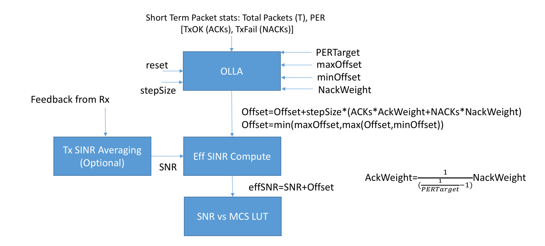
Figure 9, Transmitter Link Adaptation
Transmit Power Control
Terragraph nodes implement transmit power control (TPC) to balance two opposing requirements. The first requirement is to maximize the utilization of each transmit opportunity by using the highest MCS providing minimal error rates. The second requirement is to minimize the interference caused by transmissions at nodes other than the intended receiver. Meeting the first requirement generally requires greater transmit power to increase the SNR at the intended receiver. Meeting the second requirement generally requires reducing the transmit power to reduce interference at nodes other than the intended receiver. The algorithm used by Terragraph nodes for TPC operates in several phases.
TPC Phase 0
This phase of TPC occurs during beamforming acquisition. In this phase, the node shall use the maximum allowable transmit power for the MCS of each transmission. At the conclusion of beamforming acquisition, the nodes exchange Micro-route Exchange frames (see Micro-route Ordering Exchange and MAC & PHY Specification).
TPC Phase 1
This phase of TPC occurs after the exchange of Micro-route Exchange frames at the conclusion of beamforming acquisition. In phase 1, the nodes shall attempt to reduce transmit power, using the received signal strength indication (RSSI) indicated by the peer node and returned in the Micro-route Exchange frame and a reference value for the RSSI expected at the peer node. If the RSSI indicated by the peer node is greater than the reference RSSI value, the difference between the two RSSI values is calculated. The algorithm reduces the difference to the maximum allowable power reduction step size, if the difference is greater than the allowable step size. In this phase, power the algorithm only reduces transmit power, as needed.
if ((peerStfSnrQ2 > tp->refStfSnrStep1Q2) &&
    (peerRssiQ2 > tp->refRssiQ2)) {
     delPowerQ2 = (peerRssiQ2 - tp->refRssiQ2);
     if (delPowerQ2 > tp->delPowerStep1Q2) {
         delPowerQ2 = tp->delPowerStep1Q2;
    }
}
TPC Phase 2
This phase of TPC occurs after the exchange of the Association Request, Response, and Response Ack frames. In phase 2, the nodes shall attempt to reduce transmit power, using the SNR value returned by the peer node in the Association Response or Association Response ACK frame and a reference SNR value for the MCS expected at the peer node to provide a high probability of error-free reception. If the SNR indicated by the peer node is greater that the reference SNR value, the difference between the two SNR values is calculated. The algorithm reduces the difference to the maximum allowable power reduction step size, if the difference is greater than the allowable step size. In this phase, the algorithm only reduces transmit power, as needed.
if (updEvt == TPC_UPD_AFTER_ASSOC) {
        if (peerStfSnrQ2 > tp->refStfSnrStep2Q2) {
            delPowerQ2 = (peerStfSnrQ2 - tp->refStfSnrStep2Q2);
            if (delPowerQ2 > tp->delPowerStep2Q2) {
                delPowerQ2 = tp->delPowerStep2Q2;
            }
        }
}
TPC Phase 3
This phase of TPC occurs after the link between the peer nodes is active and the nodes exchange Heartbeat, Keep Alive, and/or Uplink Bandwidth Request frames. In phase 3, the nodes shall attempt to increase and reduce transmit power, as required, to maintain the peer SNR minimally greater than the reference SNR value. The algorithm speculatively calculates a power reduction value by calculating the difference between the peer SNR value and the reference SNR value.
If the peer SNR value is greater than the reference value, the power reduction value is the minimum of the maximum allowable step value and the speculative power reduction value reduced by a hysteresis amount. In this case the power reduction value is used to reduce the transmit power.
If the peer SNR value is less than or equal to the reference value, the power reduction value is the maximum of the allowable step size and the speculative power reduction value increased by a hysteresis amount. In this case, the power reduction value is used to increase the transmit power.
if (updEvt == TPC_UPD_DURING_LINK_UP) {
        delPowerQ2 = peerStfSnrQ2 - tp->refStfSnrStep3Q2;
        if (delPowerQ2 > 0) {
            delPowerQ2 -= tp->tpcHysteresisdBQ2Step3;
            delPowerQ2 = MIN(delPowerQ2, tp->delPowerStep3Q2);
        } else {
            delPowerQ2 += tp->tpcHysteresisdBQ2Step3;
            delPowerQ2 = MAX(delPowerQ2, -tp->delPowerStep3Q2);
        }
}
2D Scans, Massive & Diversity Modes
The objective of 1D scans is to find the best beam/sector on the Azimuth (AZ) plane, while 2D scans search on both the Azimuth (AZ) and Elevation (EL) planes.
Massive mode refers to multiple antenna tiles connected to multiple RFICs which are combined by the baseband (BB). In Massive mode, antenna tiles are in the same plane and pointing in the same directions.
Diversity mode allows a single BB chip to operate RFIC/Antenna modules that are not in the same plane and are pointing in different directions by selecting only one of them for use at a time. The region of coverage of the different RFIC/Antenna modules may or may not overlap.
General Beamforming Firmware Flow
- There are two modes for how the RFICs are programmed with the correct antenna
weight vectors (AWVs) for a specific beam:
- Legacy mode, where vendor FW uses the board file in BRD format to load AWVs used to program the RFICs. Board files have only 61 beams.
- Codebook variant mode, where FB FW uses a master codebook of 120 beams (stored on the host in JSON format) that covers a specified scan range to load specific AWVs corresponding to that beam to program the RFICs.
- For simplicity, there is a one-time download of the master codebook from the host to FW.
- The master codebook on the host will have 120 beams.
- The main codebook configurations to support will be (as an example):
- 2D: 3 EL beams and 40 AZ beams
- 1D: 1 EL beam and 120 AZ beams
- The master codebook will be defined per tile, per Tx/Rx, and per channel.
- For either Massive or Diversity mode, beamforming consists of two stages:
- Initial Beamforming (IBF) to find coarse beams during initial link establishment, using beams 0-60
- Periodic Beamforming (PBF) to perform beam refinement
Initial Beamforming
General IBF notes:
- During IBF, FW uses beams in IBF scan range in the protocol.
- Those beams are loaded to the IBF scan range in RFIC; beams 0-60 (i.e. IBF sweep size is 61).
- Whenever a beam is programmed in slot programming for a diversity node, an
implicit mapping of the tile is determined from the beam index:
- Beams 0-29 are for
set1RficBitmap(Tile 0) and beams 30-60 are forset2RficBitmap(Tile 1) - Beams 0-29 typically has the same AWV as beams 30-59
- Beams 0-29 are for
Legacy Mode
Massive:
- Vendor FW loads beams to program RFIC from a board file that has 61 beams.
Diversity:
- Vendor FW loads beams to program RFIC from a constructed board file that has
61 beams organized as follows:
- Beams 0-29 are distinct and used for Tile 0
- Beams 30-59 are a copy of beams 0-29 and used for Tile 1
- Beam 60 is a copy of Beam 59
For both massive and diversity modes:
- Beam 38 is ignored due to vendor HW limitation.
- Beam 38 is always mapped to beam 64 due to vendor HW limitation.
2D Codebook Variant Mode
Massive:
- FB FW uses a master codebook of 120 beams at the host to load 61 beams (3 EL x 20 AZ beams + 1) to program RFIC using get/set AWV.
- FB FW skips every other beam from the master codebook to load those 61 beams.
Diversity:
- FB FW uses a master codebook of 120 beams at the host to load 30 beams (3 EL x 10 AZ beams) to program RFIC using get/set AWV for Tile 0.
- FB FW skips every fourth beam from the master codebook to load those 30 beams; beams 0-29 for Tile 0.
- FB FW copies beams 0-30 to beams 31-60 for Tile 1.
1D Codebook Variant Mode
Massive:
- Same as Codebook 1 except the 61 beams from the master codebook corresponds to 1 EL x 60 AZ beams + 1.
Diversity:
- Same as Codebook 1 except the 30 beams from the master codebook corresponds to 1 EL x 30 AZ beams + 1.
Periodic Beamforming
Fine PBF refines over the entire scan range:
- Legacy mode: FW uses beams in the same IBF scan range in RFIC; beams 0-60 already programmed by vendor FW via board file.
- Codebook variant mode: FW uses beams in the same IBF scan range in RFIC; beams 0-60 already programmed by FB from the master codebook using get/set AWV.
Relative PBF refines over Azimuth (±2):
- Legacy mode: FW uses the current beam ±2 AZ from beams in the same IBF scan range in RFIC; beams 0-60 already programmed by vendor FW via board file.
- Codebook variant mode: FW loads scan beams according to the current beam ±2 AZ from the master codebook and programs them to a scratch pad scan range starting at AWV index 69 using the updateAwv API. PBF sweeps through beams programmed to the scratch pad scan range.
Firmware Configuration Parameters
ibfProcedureType:- "0": Massive Mode
- "1": Diversity Mode
ibfCodebookVariant:- "0": Legacy Mode
- "1": 1D Codebook Variant Mode
- "2": 2D Codebook Variant Mode
- RFIC bitmap is an 8-bit mask that maps which RFIC is active.
ibfSet1RficBitmap:- Massive Mode: RFIC bitmap used for IBF and as MTPO reference tile (which is typically a middle tile), default is XIF2. ibfSet1RficBitmap = 4 for XIF2 is mapped as the reference tile.
- Diversity Mode: RFIC bitmap that corresponds to Tile 0.
ibfSet2RficBitmap:- Massive Mode: Corresponds to massive tiles configuration after MTPO calibration and PBF. ibfSet2RficBitmap = 85 for 4 tiles.
- Diversity Mode: RFIC bitmap that corresponds to Tile 1.
useUpdateAwvForPbf(should be set to 1):- "0": PBF sectors are taken from IBF scan range.
- "1": PBF sweeps through beams programmed to the scratch pad scan range.
ibfNumberOfBeams: Number of beams in the IBF scan range.maxTxPowerSet1: Used to configure single tile IBF power when operating in massive mode withset1RficBitmap != set2RficBitmap.
ibfProcedureType | ibfNumberOfBeams | ibfCodebookVariant | useUpdateAwvForPbf | ibfSet1RficBitmap | ibfSet2RficBitmap | |
|---|---|---|---|---|---|---|
| Massive w/ Legacy Mode | 0 | 61 | 0 | ignored | 4 | 85 |
| Diversity w/ Legacy Mode | 1 | 61 | 0 | ignored | bitmap for tile 0 | bitmap for tile 1 |
| Massive w/ 1D Codebook Mode | 0 | 61 | 1 | 1 | 4 | 85 |
| Diversity w/ 1D Codebook Mode | 1 | 61 | 1 | 1 | bitmap for tile 0 | bitmap for tile 1 |
| Massive w/ 2D Codebook Mode | 0 | 61 | 2 | 1 | 4 | 85 |
| Diversity w/ 2D Codebook Mode | 1 | 61 | 2 | 1 | bitmap for tile 0 | bitmap for tile 1 |
Examples
1D Codebook Variant
Master Codebook Variant 1 (1D), same for Massive and Diversity modes:
| Beam Index | Geometric Direction |
|---|---|
| 0-119 | (-45 : 0.75 : 44.25) AZ, 0 EL |
Massive board file w/ 61 beams (0-60):
| Beam Index | Angular Representation |
|---|---|
| 0-37 | (-45 : 1.5 : 9) AZ, 0 EL |
| 38 | ignored |
| 39-59 | (12 : 1.5 : 43.5) AZ, 0 EL |
| 60 | 43.5 AZ, 0 EL |
| 64 (38) | 10.5 AZ, 0 EL |
Diversity board file w/ 61 beams (0-60):
| Beam Index | Angular Representation | Tile Selected in board file | Tile selected in FW |
|---|---|---|---|
| 0-29 | (-45 : 3 : 42) AZ, 0 EL | Tile 1 & 0 | Tile 0 |
| 30-37 | (-45 : 3 : 24) AZ, 0 EL | Tile 1 & 0 | Tile 1 |
| 38 | ignored | Tile 1 & 0 | Tile 1 |
| 39-59 | (-18 : 3 : 42) AZ, 0 EL | Tile 1 & 0 | Tile 1 |
| 60 | 42 AZ, 0 EL | Tile 1 & 0 | Tile 1 |
| 64 (38) | -21 AZ, 0 EL | Tile 1 & 0 | Tile 1 |
2D Codebook Variant
Master Codebook Variant 2 (2D), same for Massive and Diversity modes:
| Beam Index | Geometric Direction |
|---|---|
| 0-39 | (-30 : 1.5 : 28.5) AZ, -18 EL |
| 40-79 | (-30 : 1.5 : 28.5) AZ, 0 EL |
| 80-119 | (-30 : 1.5 : 28.5) AZ, 18 EL |
Massive board file w/ 61 beams (0-60):
| Beam Index | Angular Representation |
|---|---|
| 0-19 | (-30 : 3 : 24) AZ, -18 EL |
| 20-37 | (-30 : 3 : 18) AZ, 0 EL |
| 38 | ignored |
| 39 | 24 AZ, 0 EL |
| 40-59 | (-30 : 3 : 24) AZ, 18 EL |
| 60 | 24 AZ, 18 EL |
| 64 (38) | 21 AZ, 0 EL |
Diversity board file w/ 61 beams (0-60):
| Beam Index | Angular Representation | Tile Selected in board file | Tile selected in FW |
|---|---|---|---|
| 0-9 | (-30 : 6 : 24) AZ, -18 EL | Tile 1 & 0 | Tile 0 |
| 10-19 | (-30 : 6 : 24) AZ, 0 EL | Tile 1 & 0 | Tile 0 |
| 20-29 | (-30 : 6 : 24) AZ, 18 EL | Tile 1 & 0 | Tile 0 |
| 30-37 | (-30 : 6 : 12) AZ, -18 EL | Tile 1 & 0 | Tile 1 |
| 38 | ignored | Tile 1 & 0 | Tile 1 |
| 39 | 24 AZ, -18 EL | Tile 1 & 0 | Tile 1 |
| 40-49 | (-30 : 6 : 24) AZ, 0 EL | Tile 1 & 0 | Tile 1 |
| 50-59 | (-30 : 6 : 24) AZ, 18 EL | Tile 1 & 0 | Tile 1 |
| 60 | 24 AZ, 18 EL | Tile 1 & 0 | Tile 1 |
| 64 (38) | 18 AZ, -18 EL | Tile 1 & 0 | Tile 1 |
Glossary
| Term | Definition |
|---|---|
| ACK | Acknowledgement; a receipt of data transmission |
| BF | Beamforming; the process of using signal propagation information between two antennas and modifying antenna characteristics to maximize the signal quality between those antennas |
| BLER | Block error rate; a ratio of the number of erroneous blocks to the total blocks received in a circuit |
| BWGD | Bandwidth grant duration |
| C-PHY | C Physical Layer; a physical layer standard based on 3-phase symbol encoding |
| E2E | End-to-End Service; a service responsible for runtime operations within a single Terragraph network |
| FW | Firmware |
| IEEE | Institute of Electrical and Electronics Engineers |
| IMS | Interference measurement scan |
| L3 | Layer 3; the network layer of the multilayered communication model |
| LA | Link adaptation; the matching of modulation, coding, and other signal and protocol parameters |
| LLC | Link level connection |
| LoS | Line of sight |
| MCS | Modulation and coding scheme |
| PBS | Periodic beamforming scan |
| PER | Packet error rate |
| RSSI | Received signal strength indication |
| SNR | Signal-to-noise ratio |
| TPC | Transmit power control |