VPP Implementation
This document describes Terragraph's datapath implementation using VPP.
Overview
Terragraph uses VPP (Vector Packet Processing framework), along with DPDK and a custom wil6210 PMD, to implement its datapath.
Versioning
Terragraph uses the NXP fork of standard VPP, with a large number of Terragraph-specific patches applied on top. The current version is NXP release 21.08-LSDK, corresponding to DPDK 20.11.2 and VPP 21.01.
Code Structure
VPP is installed via meta-qoriq/recipes-extended/vpp/vpp_21.08-lsdk.bb. There
are also some scripts related to VPP service management and startup
configuration installed via meta-qoriq/recipes-facebook/tg-vpp/tg-vpp_0.1.bb.
Terragraph builds additional features on top of VPP, summarized below:
| Name | Type | Source Location | Description |
|---|---|---|---|
vpp-tgcfg | plugin | src/vpp_plugins/tgcfg/ | Configures the Terragraph-specific slow datapath. |
vpp-chaperone | application | src/vpp_plugins/vpp-chaperone/ | Applies user configs to VPP (e.g. POP, CPE, SR) over the shared memory API. |
openr-fib-vpp | application | src/vpp_plugins/openr-fib-vpp/ | The Open/R FIB (forwarding information base) implementation for VPP. |
vpp-ptptc | plugin | src/vpp_plugins/ptptc/ | Configures PTP-TC (Precision Timing Protocol Transparent Clock) timestamping in VPP. |
vpp-esmc | plugin | src/vpp_plugins/esmc/ | Configures SyncE (Synchronous Ethernet) ESMC (Ethernet Synchronization Messaging Channel) operation in VPP. |
VPP Services
The following VPP services are managed by runit: vpp, fib_vpp, and
vpp_chaperone. Logs for each service are written to
/var/log/<service>/current by svlogd. Additionally, DPDK/PMD logs captured by
VPP are extracted from syslog and written to /var/log/vpp/vnet.log. For more
details, see Node Services.
The lifetimes of certain services are tied together:
- Restarting
e2e_minionwill also restartvpp(since the entire driver stack gets unloaded) - Restarting
vppwill also forcibly restartfib_vpp(since it uses VPP's SHM API) - Restarting
fib_vppmay re-runvpp_chaperone(on POP nodes)
Startup configuration for VPP is generated at boot time by
src/terragraph-e2e/lua/update_vpp_startup_conf.lua using parameters read from
the node configuration and node info files.
A separate coop service monitors the Linux loopback prefix for changes and
reconfigures the VPP loopback prefix if necessary by running vpp_chaperone.
Some VPP stats are scraped by the stats_agent process and published on a
ZMQ port (see Stats, Events, Logs for details).
VPP Packet Processing Graph
The flowchart below demonstrates the path that data packets take through VPP and
special hooks established in the VPP packet processing graph by the vpp-tgcfg
plugin. This is explained in detail in subsequent sections.

Stock VPP Datapath Overview
All data packets received from hardware enter VPP through the dpdk-input node.
This node normally passes data to the ethernet-input node, which then
classifies packets as IPv4, IPv6, WPA, and so on. This document will focus on
IPv6 packets, which are the primary data packet type being dealt with.
Each IPv6 packet ends up in the ip6-input node, which is mostly responsible
for determining if the packet is supposed to transit out of the node. This
involves somewhat complex logic that is covered by the "Local?" decision node,
without going into details on how this is actually implemented. For example, all
unicast packets get their destination address looked up in the IPv6 FIB. All
link-local addresses will hit an entry in the FIB that will redirect them to the
ip6-link-local node, which in turn will perform a lookup in a separate FIB to
find out if the destination address matches one of the interfaces that VPP
recognizes. If it does, the packet gets forwarded into the ip6-local node to
be handled on the node. Otherwise, the packet is for an invalid address and gets
dropped.
The FIB entry to redirect all link-local packets to ip6-link-local looks like
this:
fe80::/10
unicast-ip6-chain
[@0]: dpo-load-balance: [proto:ip6 index:7 buckets:1 uRPF:6 to:[162:22458]]
[0] [@15]: ip6-link-local
The following trace fragment demonstrates the handling of link-local packets in VPP by this path:
00:53:14:979091: ip6-lookup
  fib 0 dpo-idx 0 flow hash: 0x00000000
  ICMP6: fe80::6ce:14ff:feff:4281 -> fe80::6ce:14ff:feff:428b
    tos 0x00, flow label 0xb271e, hop limit 64, payload length 64
  ICMP echo_request checksum 0xfd87
00:53:14:979102: ip6-link-local
  sw_if_index:14 fib_index:10
00:53:14:979106: ip6-lookup
  fib 10 dpo-idx 14 flow hash: 0x00000000
  ICMP6: fe80::6ce:14ff:feff:4281 -> fe80::6ce:14ff:feff:428b
    tos 0x00, flow label 0xb271e, hop limit 64, payload length 64
  ICMP echo_request checksum 0xfd87
00:53:14:979110: ip6-local
    ICMP6: fe80::6ce:14ff:feff:4281 -> fe80::6ce:14ff:feff:428b
      tos 0x00, flow label 0xb271e, hop limit 64, payload length 64
    ICMP echo_request checksum 0xfd87
Similarly, all multicast addresses are looked up in the ip6-mfib FIB table and
either get dropped or get forwarded to ip6-local to be handled on the node:
00:52:58:405106: ethernet-input
  IP6: 04:ce:14:ff:42:81 -> 04:ce:14:ff:42:8b
00:52:58:405118: ip6-input
  UDP: fe80::6ce:14ff:feff:4281 -> ff02::1
    tos 0xc0, flow label 0x5d69e, hop limit 255, payload length 171
  UDP: 6666 -> 6666
    length 171, checksum 0x63e7
00:52:58:405128: ip6-mfib-forward-lookup
  fib 0 entry 4
00:52:58:405136: ip6-mfib-forward-rpf
  entry 4 itf 14 flags Accept,
00:52:58:405144: ip6-replicate
  replicate: 2 via [@1]: dpo-receive
00:52:58:405153: ip6-local
    UDP: fe80::6ce:14ff:feff:4281 -> ff02::1
      tos 0xc0, flow label 0x5d69e, hop limit 255, payload length 171
    UDP: 6666 -> 6666
      length 171, checksum 0x63e7
All known unicast addresses for existing interfaces in VPP will get an entry in
the IPv6 FIB, similar to this one, which will redirect matching packets to the
ip6-local node as well:
71::3/128
  unicast-ip6-chain
  [@0]: dpo-load-balance: [proto:ip6 index:66 buckets:1 uRPF:71 to:[3:312]]
    [0] [@2]: dpo-receive: 71::3 on loop1
A sample trace fragment is given below:
01:21:15:353214: ethernet-input
  IP6: 04:ce:14:ff:42:81 -> 04:ce:14:ff:42:8b
01:21:15:353224: ip6-input
  ICMP6: 2801:b8:fb:fb9c::1 -> 71::3
    tos 0x00, flow label 0x27108, hop limit 63, payload length 64
  ICMP echo_request checksum 0xbd02
01:21:15:353233: ip6-lookup
  fib 0 dpo-idx 5 flow hash: 0x00000000
  ICMP6: 2801:b8:fb:fb9c::1 -> 71::3
    tos 0x00, flow label 0x27108, hop limit 63, payload length 64
  ICMP echo_request checksum 0xbd02
01:21:15:353243: ip6-local
    ICMP6: 2801:b8:fb:fb9c::1 -> 71::3
      tos 0x00, flow label 0x27108, hop limit 63, payload length 64
    ICMP echo_request checksum 0xbd02
01:21:15:353252: tg-slowpath-terra-rx
The important takeaway from the above examples is as follows: any packet that is
to be handled on the node itself eventually goes though a FIB lookup that
returns a dpo-receive object. This tells VPP that the packet should be handled
by the ip6-local node as the next step. The DPO ("data-path object") also
encodes the interface for which the packet is received, so upon entry
ip6-local knows the interface that has received the packet and the interface
for which the packet was sent.
All other packets either match a valid entry in the FIB and are forwarded to the appropriate interface to be sent out, or they are dropped as invalid.
Terragraph Config Plugin (vpp-tgcfg)
The vpp-tgcfg plugin installs several hooks into the VPP packet graph and
configures certain interfaces and their properties on startup. The primary goal
for these is to handle the Terragraph-specific slow datapath, where some traffic
is handled entirely in VPP (fast path) and some gets forwarded to the Linux
kernel to be handled there (slow path).
The slow path is enabled by default. It can be switched off by adding the "slowpath" directive in the "terragraph" section of VPP's startup configuration:
terragraph {
  slowpath off
}
Interfaces
VPP maintains several "split-level" interfaces:
vpp-terraXinterfaces, representing Terragraph links. Each instance of avpp-terraXinterface has a correspondingterraXinterface on the Linux side. The plugin uses a side-channel interface with the wil6210 PMD anddpdk-dhd.kokernel module to receive packets from the kernel and to inject packets into the kernel on behalf ofterraX.vpp-nicXtap interfaces, and correspondingnicXendpoints on the Linux side. These represent wired Ethernet interfaces and use VPP's built-intapclimodule to read and inject packets.vpp-vnet0tap interfaces, and correspondingvnet0endpoints on the Linux side. This pair is used for L3-routable connection between vpp and the Linux kernel. Namely, DNs and CNs will have a default route pointing tovnet0.loop0, a VPP interface that serves as a pure VPP-only L3-routable endpoint. It gets assigned a::2address from the node's prefix for that interface by another process (vpp_chaperone). The only useful function of this interface at the time of this writing is to serve its global IPv6 address to the ICMPv6 error source address selection algorithm.
Configuration
The VPP plugin identifies all Wigig interfaces at startup time, establishes a
side-channel API connection to corresponding PMD and consequently dpdk-dhd.ko
running in the kernel automatically. This auto-probe can be switched off by
adding the "auto-probe off" directive in the "terragraph" section of VPP's
startup configuration:
terragraph {
  auto-probe off
}
VPP creation of the vpp-vnet0/vnet0 tap interface pair is enabled by the
following directive in the startup configuration:
terragraph {
  host interface vnet0
}
The vpp-nic0/nic0 tap interface pair is created by the following directive
in the startup configuration:
terragraph {
  interface TenGigabitEthernet0 {
    tap nic0
  }
}
The directive example above will create nic0 on the kernel side and vpp-nic0
in VPP, and arrange for slow path processing similar to processing done for
Wigig/vpp-terra0/terra0. The MAC address of the nic0 interface in the
kernel will match the MAC address of the corresponding TenGigabitEthernet0
interface in VPP.
Graph Nodes
The following section lists the graph nodes that vpp-tgcfg implements, their
functions, and where they are connected into the packet processing graph.
tg-link-input
This node intercepts all packets received from WigigX/Y/Z/0 interfaces and
examines packet metadata to find out what vpp-terraX interface should be
marked as the receiving interface for the packet. The packet metadata is stored
in the rte_mbuf structure using a custom dynamic field (or dynfield). It
then forwards the packets to the normal VPP data processing path, namely the
ethernet-input node. As far as VPP is concerned, the packets are received by
proper vpp-terraX interfaces from now on.
The node is inserted into the graph by a call in the tg_interface_enable()
function:
  /* Let incoming traffic to be assigned to correct link interface */
  vnet_feature_enable_disable ("device-input", "tg-link-input", sw_if_index,
                               enable_disable, 0, 0);
tg-slowpath-wired-rx, tg-slowpath-terra-rx
These two nodes intercept all packets from vpp-terraX and slow path-enabled
wired ports hitting the ip6-local node, before any processing has been done
for them. These nodes examine the interface addressed by the packet and if it
happens to belong to any slow path-enabled interface, the packet is forwarded to
tg-link-local-tx or tg-wired-local-tx nodes for packets received over Wigig
or over wired ports, respectively. The packet will then be forwarded to the
kernel and inserted into the Linux stack as appropriate.
Packets addressed to any other interface are processed by VPP locally. Packets
addressing loop0 fall into this category.
Instantiated as features on the ip6-local arc in the
tg_wired_interface_enable() and tg_interface_enable() functions.
tg-link-local-tx
This node accepts packets and calls into the PMD/dpdk-dhd to get them delivered
to the kernel. The kernel module then injects packets onto the Linux networking
stack using netif_rx on behalf of the proper terraX interface. The node is
scheduled as the next node explicitly by tg-slowpath-terra-rx when necessary.
tg-wired-local-tx
This node accepts packets that came from a slow path-enabled wired port (e.g.
TenGigabitEthernet0), and forwards them to the interface output of the
corresponding vpp-nicX interface. This in turn will make tapcli-tx send
packets over to the Linux side and be inserted into the Linux kernel stack on
behalf of the matching nicX interface. The node is scheduled as the next node
explicitly by tg-slowpath-wired-rx when necessary.
vpp-terra-tx
This node accepts all packets that VPP wants to be sent over the air using one
of the vpp-terraX interfaces as the source. Since vpp-terraX are virtual
interfaces representing the link, the node performs a function logically
opposite to that of the tg-link-input node: it uses vpp-terraX information
to mark the packet with the desired link to be used and then forwards the packet
to WigigX/Y/Z/0 for actual transmission.
This is not an actual node, but rather a TX function tg_link_interface_tx()
registered as the output handler of the vpp-terraX interface class. VPP
creates vpp-terraX-tx nodes with this function as the handler automatically.
VNET_DEVICE_CLASS (tg_link_interface_device_class) = {
    .name = "TGLink",
    .format_device_name = format_tg_link_name,
    .format_tx_trace = format_tg_link_tx_trace,
    .tx_function = tg_link_interface_tx,
    .admin_up_down_function = tg_link_interface_admin_up_down,
};
tg-link-local-rx
This node gets scheduled every time the kernel wants to send packets over any
terraX interface. The dpdk-dhd.ko will relay them into the AF_PACKET queue
and make the queue socket FD readable, and that eventually results in VPP
invoking the node's tg_link_local_rx() function. It will fetch all packets
from the kernel, convert them into VPP buffers, mark them with the proper link
interface, and invoke TX on the real Wigig interface.
      clib_file_main_t *fm = &file_main;
      clib_file_t template = {0};

      template.read_function = tg_link_local_rx_fd_read_ready;
      template.file_descriptor = wi.data_fd;
      template.description = format (0, "%s", "wigig-local-rx");
      template.private_data = vec_len (tm->wigig_devs);

      wdev.clib_file_index = clib_file_add (fm, &template);
tg-wired-local-rx
This node intercepts packets received from the nicX tap interface and sends
them directly over the corresponding wired port. It is similar in function to
tg-link-local-rx, but for wired interfaces.
Instantiated in the tg_wired_interface_enable() function in the plugin.
HQoS Scheduler (TGHQoS)
Terragraph uses a custom Hierarchical Quality-of-Service (HQoS) scheduler on
traffic transmitted out of Wigig interfaces for managing prioritization of
different traffic types. The implementation is originally based on VPP's
now-deprecated HQoS functionality that used the DPDK QoS framework implemented
in DPDK's librte_sched library.
Code Structure
The HQoS implementation exists as a separate module within VPP's DPDK plugin. It
is included as a series of patches in
meta-qoriq/recipes-extended/vpp/vpp_19.09-lsdk.bb, with code added into the
directory vpp/src/plugins/dpdk/tghqos.
Hierarchy
The HQoS scheduler has 4 hierarchical levels, consisting of (1) port, (2) pipe, (3) traffic class, (4) queue. A port is a Wigig device, and a pipe is a Wigig peer. Packet IPv6 DSCP headers are used to classify packets into different traffic classes with 3 different colors. Currently Terragraph uses 4 traffic classes with 1 queue per traffic class. The color is coded as the drop precedence of the packet in accordance with RFC 2597.
RED Dropper
To avoid congestion, packets arriving at the scheduler go through a dropper that
supports Random Early Detection (RED), Weighted Random Early Detection (WRED),
and tail drop algorithms. The RED dropper is the same as the original one in
librte_sched, ported into VPP to decouple the HQoS implementation from any
specific DPDK libraries.
CLI Commands
The HQoS scheduler has many associated CLI commands for configuration, testing,
and stat collection purposes. The HQoS-specific CLI commands are provided in and
documented in tghqos_cli.c, including example command invocations and outputs.
HQoS Operation
The HQoS scheduler is logically part of the VPP Wigig output interface. When a
packet is directed to a Wigig interface for tx (WigigX/Y/Z/0-tx), it will
first go through the HQoS scheduler before being passsed to the driver for
transmission.
The HQoS scheduler performs classification, enqueue, and dequeue operations on
each packet. For classification, the scheduler reads the mbuf's link id metadata
stored in a dynfield of the mbuf to determine the pipe to which the packet is
assigned, and it maps the DSCP value to the appropriate traffic class, queue,
and color. This information gets stored in the mbuf's sched field. The enqueue
operation uses this information to store the packet in the appropriate queue,
dropping the packet as the RED dropper algorithm deems necessary or if the queue
is full. The dequeue operation currently uses strict priority scheduling by
default, where packets are dequeued from the HQoS scheduler in strict priority
order according to traffic class. Since the Wigig driver has separate transmit
rings for each peer, the HQoS scheduler uses feedback from the driver about each
transmit ring's occupancy to determine how many packets to dequeue for each
pipe. Note that the traffic class prioritization is thus applied within each
pipe independently, and not across all pipes at once. After packets are dequeued
from the HQoS scheduler, they are passed to the driver for transmission.
Weighted round robin scheduling with priority levels is also provided as an option. Traffic classes are assigned a priority level and a weight. Traffic classes at a higher priority level are served before traffic classes at a lower priority level. Traffic classes at the same priority level are served in accordance to assigned weight. Each traffic class must have a non-zero weight in one priority level. Besides that requirement, weights can be arbitrary non-negative integers; for each traffic class the scheduler will use the proportion of its weight to the sum of weights in that priority level to determine the proportion of packet segments that traffic class can send during each transmission period.
By default, the HQoS operations for a Wigig device run in the VPP node graph on the same worker thread used for its rx processing, but it can also be configured to use separate threads (see Interface Thread Assignment).
Wigig Jumbo Frame Support
The Wigig device software has an MTU of 4000 bytes, so any packets of length greater than 4000 are considered jumbo frames that must be segmented before being transmitted across a Wigig link.
VPP and DPDK Buffers
Packets are represented as DPDK rte_mbuf structs, and each rte_mbuf has 2176
bytes of data space in VPP. Packets of total packet length greater than 2176 are
represented as a chain of rte_mbuf segments. Multi-segment packets are also
chained with vlib_buffer_t linkage for processing in VPP.

After VPP receives packets via dpdk-input, the vlib buffer's current_data
offset pointer, which is used as the start of data to be processed in VPP, is
set to mbuf->data_off - 128
(RTE_PKTMBUF_HEADROOM = VLIB_BUFFER_PRE_DATA_SIZE = 128):
b[0]->current_data = mb[0]->data_off - RTE_PKTMBUF_HEADROOM;
This refers to the same address as mbuf->buf_addr + mbuf->data_off.
Jumbo Frame Segmentation
Jumbo frames can be easily segmented by cutting the mbuf linkage along the mbuf chain. After inserting a custom header, these segments can be enqueued for transmission as individual packets.
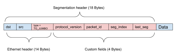
Segmented Terragraph jumbo frame packets are identified by the custom Ethernet
type 0xFF71 (TG_JUMBO). Since segmented Terragraph packets exist only on a
Wigig segment between two TG nodes, the value of the Ethernet type itself is not
important. The combination of the custom fields packet_id, seg_index, and
last_seg are used in segmentation and reassembly. A protocol_version field
is included for futureproofing.
The current maximum supported jumbo frame packet size in VPP is about 18KB. This
is determined by the number of segments that can be stored according to
TG_JUMBO_FRAME_SEG_ARRAY_LEN.
Transmitting / Segmentation
Segmentation is done prior to the input of the HQoS transmit queue in the DPDK plugin. Jumbo frames are identified by packet length and are segmented by breaking the mbuf chain. Custom segmentation headers are prepended to each segment's packet data.
There is no guarantee that each segment has sufficient headroom to fit the
segmentation header, so packet data must be shifted to allow for enough space
for the header. Each rte_mbuf would typically be allocated
RTE_PKTMBUF_HEADROOM (128) bytes of headroom, but drivers may choose to leave
0 bytes of headroom for noninitial segments (e.g. DPAA2 driver). Accordingly,
segments that require data shifting will likely not have enough tailroom, and
will require the tail end of its packet data to be copied to the next segment.
After cutting segment chains, shifting and copying data, and inserting headers,
segments are enqueued to the HQoS transmit queue as individual packets. No
further VPP node processing will occur so there is no need to address
vlib_buffer_t linkage.
Receiving / Reassembly
Reassembly is done as soon as packets are received from the driver in the DPDK plugin, prior to injecting the packet into the rest of the VPP node graph. Only one fragmented packet can be in flight at a time, per flow. Since the Wigig has no concept of traffic class, there is a maximum of one fragmented packet per peer per sector.
After an array of mbufs is received from the driver, jumbo frame segment packets
are identified by their Ethernet type and removed from the mbuf processing
array. They are stored in an array per device according to the link id found in
a dynfield of the mbuf and its seg_index field. After a segment with the
last_seg field set is received, reassembly is attempted by first checking that
there is a segment for every prior index, and verifying all stored segments have
the same packet_id. Then, create the linkage for the packet by chaining the
mbufs, and increment each mbuf segment's data_off field to skip over the custom
segmentation header.
The reassembled single packet is then passed on to dpdk_process_rx_burst for
further processing, including creating vlib_buffer_t linkage.
VPP Threads & Core Allocation
The table below lists all VPP and PMD threads along with their CPU core allocation on Puma hardware (4 cores).
| Thread Name | Core # | Purpose |
|---|---|---|
vpp_main | 1 | Handles CLI, Wigig, and network events, etc. |
vpp_wk_X | 2-3 | Datapath workers (one per CPU core) |
eal-intr-thread | 0 | Primary PCI interrupt dispatcher |
wil6210_wmiX | 1 | Interrupt handlers (one per Wigig card) |
poll-dhdX | 1 | ioctl dispatcher (one per Wigig card) |
wil-fw-log-poll | 1 | Firmware/ucode log polling (one per Wigig card) |
nl60g-poll | 1 | Communicate with host_manager_11ad utility (one per Wigig card) |
The core allocation is set by update_vpp_startup_conf.lua using the VPP
configuration options cpu skip-cores, cpu workers, and
dpdk dev <pci_id> workers. Threads created by the PMD are set to use the
master lcore ("logical core") for DPDK, i.e. the core used for vpp_main.
On Puma, CPU cores 2 and 3 are reserved for the datapath, enforced by passing
isolcpus=2,3 in the Linux kernel configuration. Most user processes are
expected to run on CPU core 1, configured by runit via taskset (refer to
runit scripts for more
details). However, the remaining core is not used for the datapath, as several
firmware crashes have been observed when reserving three datapath cores.
Interface Thread Assignment
When an interface is assigned to a worker thread, its rx processing begins on that thread, and packets received on that interface continue through the VPP node graph on that thread. When these packets are directed to tx interfaces without HQoS enabled, they are sent to the driver of the tx interface on the same thread as it was received.
When these packets are directed to tx interfaces with HQoS enabled, packets are not immediately sent to the driver, and the next immediate step is determined by whether there are separate HQoS threads enabled:
- No HQoS thread enabled - Packets are enqueued into HQoS queues. Packets
are dequeued from HQoS queues and sent to the device driver during the
execution of the
dpdk-inputpolling node associated with the tx interface. This happens on the worker thread to which its rx processing was assigned, not the worker thread on which the packet was originally received. - HQoS thread enabled - Packets are passed to the HQoS thread via a software queue in VPP. The separate HQoS thread will receive these packets and handle enqueuing into HQoS queues, dequeueing from HQoS queues, and sending to device drivers.
The current default configuration has HQoS enabled on Wigig devices and no HQoS
threads enabled. HQoS threads can be enabled by using the
cpu corelist-tghqos-threads option in VPP's startup configuration and moving
all interface rx processing onto one worker thread. Enabling HQoS threads may be
beneficial for certain types of traffic, particularly with small packet sizes on
nodes with 1 or 2 Wigig sectors, but performance suffers when passing traffic at
maximum throughput on 3 or 4 sectors.
Firmware Message Paths
This section describes the flow of firmware ioctl calls (initiated by
user-space programs) and firmware events (initiated by firmware) within VPP. For
a system-level view of these message paths, refer to
Driver Stack.
Firmware ioctl
Firmware ioctl calls are initiated from user-space programs (e.g. e2e_minion)
and require a completion notification from firmware. The path is as follows:
| Sequence | Entity | Actions |
|---|---|---|
| 1 | poll-dhdX | Wake on dhdX network interface wmi_send()Write ioctl message to PCI |
| 2 | Wigig firmware | Process ioctl and generate completion event |
| 3 | eal-intr-thread | Wake on VFIO_MSI interruptRead firmware message from PCI Dispatch to per-interface work thread |
| 4 | wil6210_wmiX | Wake on Linux futex (pthread_cond_wait())Read firmware message from work queue Process completion event |
| 5 | poll-dhdX | Wake on Linux futex (pthread_cond_wait())Send completion event to driver |
Firmware Event
Firmware events are initiated by firmware and do not require a completion notification. The path is as follows:
| Sequence | Entity | Actions |
|---|---|---|
| 1 | Wigig firmware | Generate event |
| 2 | eal-intr-thread | Wake on VFIO_MSI interruptRead firmware message from PCI Dispatch to per-interface work thread |
| 3 | wil6210_wmiX | Wake on Linux futex (pthread_cond_wait())Read firmware message from work queue Send event to driver |
Debugging
This section briefly describes possible debugging options for VPP.
Use Debug Builds
Recompile VPP and any plugins (ex. vpp-tgcfg) with debug information by adding
these lines to conf/local.conf:
DEBUG_BUILD_pn-vpp = "1"
DEBUG_BUILD_pn-vpp-tgcfg = "1"
Enable Core Dumps
VPP core dumps can be enabled via the node configuration field
envParams.VPP_COREDUMP_ENABLED (enabled by default). Core dumps are written to
/var/volatile/cores/ and can be loaded into gdb.
Collect Packet Traces
VPP allows collecting packet traces at different points of the datapath using
the "trace" commands (e.g. trace add <node>, show trace, clear trace).
Some important graph nodes include:
dpdk-input: All traffic arriving into VPP from wired or wigig interfacestg-link-local-rx: All traffic arriving into VPP fromterraXinterfaces on the Linux sidetapcli-rx: All traffic arriving into VPP from thevnet0interface on the Linux sidevpp-terraX-tx: All traffic generated in VPP forvpp-terraXinterfaces (replace X with the actual index)pg-trace: All traffic generated by VPP's packet generator
Resources
- DPDK - Data Plane Development Kit
- DPDK QoS Framework - DPDK QoS Framework implemented in
librte_sched - VPP - Vector Packet Processing
- Open/R - Meta's routing platform